PRESENTATION ON FREQUENCY CONTROL AND
PRESENTATION ON FREQUENCY CONTROL AND FREE GOVERNOR OPERATION TO THE OFFICERS OF CENTRAL ELECTRICITY AUTHORITY On 4 th April, 2005. by V.K. Agrawal SRLDC, Bangalore. FREE GOVERNOR OPERATION THE BASICS. VARIATION IN FREQUENCY. Sudden addition of load causes a drop in frequency.


PRESENTATION ON FREQUENCY CONTROL AND
E N D
Presentation Transcript
PRESENTATION ON FREQUENCY CONTROL AND FREE GOVERNOR OPERATIONTO THE OFFICERS OFCENTRAL ELECTRICITY AUTHORITY On 4th April, 2005 by V.K. Agrawal SRLDC, Bangalore
VARIATION IN FREQUENCY • Sudden addition of load causes a drop in frequency. • An increased load is supplied through an increase in the load angle by which the rotor lags the stator field. • It means a loss of Kinetic Energy of the rotating M/c and a slower speed of rotation i.e. a lower frequency. f = (P/2) X (N/60) Where f = frequency of the system P = no of poles of the M/c. N = rpm of the M/c.
PRIMARY CONTROLSTO REGULATE FREQUENCY • Relief by frequency dependent load • Free Governor Operation • Under Frequency Operation
GOVERNOR • Speed governor is the controlling mechanism which controls the input to the prime mover automatically when there is a change in system speed (frequency) • When there is a change in speed (frequency), governor responses by causing valves/gates to open/close to increase/decrease the input to the prime mover • The notion that Governor attempts to restore frequency to normal is a misconception. In reality, Governors attempts to restore load generation balance, using frequency change as a signal.
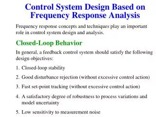
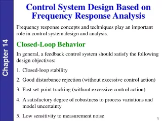
PRIMARY CONTROL - GOVERNOR ACTION Primary control involves the action of turbine speed governors in generating units, which will respond when the current speed (frequency) deviates from the set point speed (frequency) due to an imbalance between the generation and demand. In a synchronously interconnected network the technical solidarity between members will involve the simultaneous action of primary control on all generating units and thereby minimising the net effect on each unit.
DROOP • Droop is the amount of speed (or frequency) change that is necessary to cause the main prime mover control mechanism to move from fully closed to fully open. • Normal range - 3 to 5%
FREQUENCY VS LOAD CURVE Load in % 100% Droop = 5% 50% Frequency in Hz 0% 52.5 Hz 50 Hz 51.25 Hz
400 300 200 160 120 100 80 40
GOVERNING SYSTEM • Hydraulic system has a droop of 5% • Electro-hydraulic system has a droop adjustable from 2.5 to 8%. It is normally set at 5% • In ehtc, droop characteristics is realised through frequency influence on load controller • Frequency influence also acts in cmc for combustion controls
BLOCKED GOVERNOR Blocking of governor is bypassing the governing feedback mechanism to maintain fixed generator output.
DROOP • The definition of DROOP is the amount of speed (or frequency) change that is necessary to cause the main prime mover control mechanism to move from fully closed to fully open. In general, the percent movement of the main prime mover control mechanism can be calculated as the speed change (in percent) divided by the per unit droop.
REGULATION • The term SPEED REGULATION refers to the amount of speed or frequency change that is necessary to cause the output of the synchronous generator to change from zero output to full output. In contrast with droop, this term focuses on the output of the generator, rather than the position of its valves. In some cases, especially in hydro, the droop setting will be significantly different from the resulting speed regulation. This is due to the nonlinear relationship between valve position and water, gas or steam flow through the turbine.
EFFECT OF DIFFERENT DROOP SETTINGS:-2 UNIT EXAMPLE INITIAL OPERATING POINT BOTH UNITS AT 500 MW, 50 HZ FINAL OPERATING POINT UNIT 2 AT 5% DROOP GENERATION IN MW 333 FINAL OPERATING POINT UNIT 1 AT 3% DROOP FREQUENCY