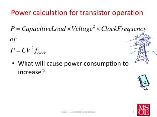
Operation Transistor
This document details the design, construction, and performance analysis of a three-stage differential amplifier using PMOS and NMOS transistors. Each stage is carefully designed for optimal biasing and amplification, with specific emphasis on matching drain currents, implementing current mirrors, and minimizing crossover distortion. Key features include the use of a Miller capacitor for frequency response optimization and step-by-step adjustments of gate-source voltages via potentiometers. The resultant amplifier achieves significant differential gain and demonstrates effective linearity and stability through careful component selection.

Operation Transistor
E N D
Presentation Transcript
Operation Transistor Matthew Ladew Philip Hart Jenniffer Estrada
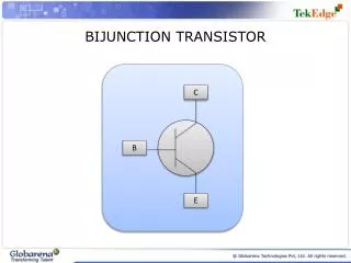
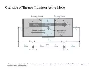
Stage 1 Amplifier • Pmos transistors MP1 and MP2 ensure identical biasing drain currents for MND1 and MND2 • Active load- behaving as a current-stable nonlinear resistor • Act similarly to a current mirror • Nmos transistors MND1 and MND2 act as differential pair • Common mode and differential mode can be considered separately using superposition • Differential gain is given by: • Current Source • Uses a current mirror to supply a constant dc biasing current to differential amplifier Fig. 1: Stage one, the differential amplifier and current source Gain of stage one: 29 V/V
Current Mirror • MN2 matches reference current provided by MN1 • Since MN2 has the same gate-source voltage, the drain current must be identical • Potentiometer Rref adjusts this gate-source voltage to obtain desired reference current • As long as MN2 remains in saturation, drain current will be mirrored Fig. 2. Current mirror schematic
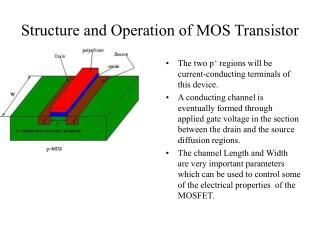
Stage 2 Amplifier • Pmos MP3 added in common source configuration • Inverting gain • Drain current, IDP3, determined by ratio: (W/L)P3/(W/L)P1 • MP3 not doubled in width: only one transistor in the CD4007 chip used • Nmos MN3 supplies a mirrored source current • Drain current, IDN3, determined by (W/L)N3/(W/L)N1 • Good match occurs when drain currents IDP3 and IDN3 are identical, which results in DC bias voltage of zero at output VO2 • Significant mismatch between transistors MP1 and MP3 resulted in poor gain, we eventually replaced MP1 to achieve a much higher gain Fig. 3 Two stage amplifier with second stage, common source amplifier on the right side of the schematic Gain of stage two: -35 V/V
Stage 3 Amplifier • Push pull structure added by MP4 and MP4 • Adds low output impedance • Crossover distortion minimized by correct value of RGG • Potentiometers RGG and Rref were tuned in succession several times so that VGG > 1.1(Vtn + ⎟Vtp⎜) and VO = 0. Fig. 4 Complete three stage amplifier, with third and final stage Stage 3 Gain: 1800 V/V
Screenshot- Third Stage Without RGG With RGG Third stage: Yellow trace is Vo2+, Green is Vo, purple is Vo2+ - Vo; this demonstrates the effect of RGG on the crossover distortion.
Miller Capacitor • Miller capacitor added between outputs of first and second stages • Adds a pole to the bode plot to place the 3db point to a lower frequency • Prevented feedback oscillation
Non-Inverting Op-Amp • R1 = 2Kohm • R2 = 200ohm • Vin at non-inverting input V2, R2 connected from inverting input V1 to ground
Inverting Op-Amp • Rf = 2Kohm • Ri = 200ohm • Non-inverting input at V2 grounded, Ri connected between inverting input V1 and Vin