Two-Dimensional Viewing and Clipping Techniques
370 likes | 697 Vues
Explore the concept of two-dimensional viewing and clipping in computer graphics, including window-to-viewport mapping, transformation of geometric primitives, and clipping algorithms for points, lines, and polygons. Discover the tools and methods used to render objects in a defined display area, ensuring device independence and efficient rendering processes.

Two-Dimensional Viewing and Clipping Techniques
E N D
Presentation Transcript
Two Dimensional Viewing and Clipping.
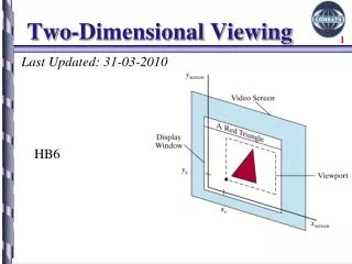
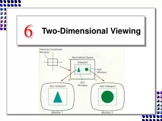
Two-Dimensional Viewing and Clipping Much like what we see in real life through a small window on the wall or the viewfinder of a camera, a computer generated image often depicts a partial view of a large scene. 2) Objects are placed in to scenes by modelling transformations to a master co-ordinate system, commonly referred to as world co-ordinate system. 3) An image Representing a view often becomes part of a larger image, like a photo on an album page, which models a computer monitors display area. Since the monitor sizes differ from one system to another, we want to introduce a device independent tool to describe a display area . This tool is called normalized device co-ordinate system. 4) The process that converts object co-ordinate in WCS to normalized device co-ordinates is called window to viewport mapping 5) A world co-ordinate area selected for display is called window. An area on a diplaydeivice to which a window is mapped is called a viewport.
window viewport device coordinates world coordinates Need device independence.
Transform 2D Geometric Primitives from Screen Coordinate System (Projection Coordinates) to Image Coordinate System (Device Coordinates) Viewport Transformation Image Screen Viewport
Window World-coordinate area selected for display What is to be viewed Viewport Area on the display device to which a window is mapped Where it is to be displayed Window vs. Viewport
Window to viewport Mapping 1) A window is specified by four world co-ordinates : Wxmin, Wxmax, Wymin, Wy max. 2) Similarly a viewport is specified by four normalized device co-ordinate : Vxmin, Vxmax, Vymin, Vymax. 3) The objective of window to viewport mapping is to convert the world co-ordinates (Wx,Wy) of an arbitrary point to its corresponding normalized device co-ordinate(Vx,Vy). Wx-Wxmin/Wxmax-Wxmin = Vx-Vxmin/Vxmax-Vxmin Wy-Wymin/Wymax-Wymin= Vy- Vymin/Vymax-Vymin Thus Vx=Vxmax-Vxmin/Wxmax-Wxmin(Wx-Wxmin)+Vxmin Vy=Vymax-Vymin/Wymax-Wymin(Wy-Wymin) + Vymin.
The above Equation can also be derived with a set of transformation theta converts the window area in to the viewport area. • Perform a scaling transformation using fixed point position that scales the window area to the size of viewport. • Translate the scaled window area to the position of the viewport. • Sx=vxmax-vxmin/wxmax-wxmin • Sy=vymax-vymin/Wymax-Wymin
1) Point Clipping: • 2) Line Clipping • Cohen Sutherland Algorithm (Line) • Mid-Point Sub Division Algorithm • 3) Polygon Clipping • Sutherland-Hodgeman Algorithm (Polygon) • Weiler Atherton Algorithm • 4) Text Clipping Clipping:The Clipping operation eliminates objects or portions of objects that are not visible through .the window
Point Clipping For a point (x,y) to be inside the clip rectangle:
Point Clipping For a point (x,y) to be inside the clip rectangle:
Line Clipping Cases for clipping lines
Line Clipping Cases for clipping lines
Line Clipping Cases for clipping lines
Line Clipping Cases for clipping lines
Line Clipping Cases for clipping lines
Line Clipping Cases for clipping lines
Cohen-Sutherland Algorithm • In this algorithm we divide the line Clipping Process in to Two Phases. • Identify Those Lines which intersect the clipping window and so need to be clipped. • Perform the Clipping. All Lines Fall in to one of the following Categories: • Visible: Both the end points of the line Lie with in the window. • Not Visible: The Line Definitely Lies outside the window. This will occur if the line from (x1,y1) to (x2,y2) satisfies any one of the following four inequalities. x1,x2>Xmax , x1,x2 <Xmin, y1,y2> Ymax , y1,y2<Ymin. 3) Clipping Candidate: The Line is in neither category 1 nor 2.
The algorithm employs an efficient procedure for finding the category of a line. It proceeds in Two Steps. • Assign a 4-bit Code to each endpoint of the line. The code is determined according to which of the following nine regions of the plane the endpoint lies in. Region outcodes
Starting From the left most bit each bit of the code is set to true(1) or false(0) according to scheme. • Bit1=endpoint is above the window=sign(y-ymax) • Bit2=endpoint is below the window=sign(ymin-y) • Bit3=endpoint is to the right of the window=sign(x-xmax) • Bit4=endpoint is to the left of the window=sign(xmin-x) We use the convention that sign(a)=1 if a is positive , 0 otherwise. 2) The Line is Visible if both the region codes are 0000 Not Visible if the bitwise logical AND of the codes is Not 0000. Candidate for Clipping if the bitwise Logical AND of the region Codes is 0000.
For the line in Category 3 we proceed to find the intersection point of the line with one of the boundries of the clipping window. • If bit 1and 2 is 1 then intersect with Line y=ymax and y= ymin. • If bit 3and 4 is 1 then intersect with Line x=xmax and x= xmin. • The co-ordinates of the intersection points are: • xi= xmin or xmax (if the boundary line is vertical: • Yi=y1+m(xi-x1); Or xi= x1+(yi-y1)/m ( if the boundary line is horizontal) Yi=ymin or ymax; Where m is slope = (y2-y1)/(x2-x1)
Cohen-Sutherland Algorithm An Example
Cohen-Sutherland Algorithm An Example
Cohen-Sutherland Algorithm An Example
Cohen-Sutherland Algorithm -1,7 6 -4,2 1 -3 2 An Example
Polygon Clipping Example
Polygon Clipping Example
Polygon Clipping Example
Clip Against Bottom Clipping Boundary Clip Against Right Clipping Boundary Clip Against Top Clipping Boundary The Clipped Polygon Clip Against Left Clipping Boundary Initial Condition Sutherland-Hodgeman Algo.
Case 1 Case 2 Case 3 Case 4 4 Cases of Polygon Clipping
Algorithm Begin with the initial set of verteces Define the category of the line as per the diagrams. Clip the polygon against left rectangle boundary to produce new set of verteces. Pass this new set of verteces to right, bottom, and top Boundary for clipping and generating new verteces during each clipping process.
Weiler Atherton Polygon Clipping The Basic idea in this algorithm is that instead of always proceeding around the polygon edges as vertices are processed, we sometimes want to follow the window boundaries. Which path we follow depends on the polygon-processing direction and whether the pair of polygon vertices currently being processed represents an outside to inside pair or an inside to outside pair. String Clipping: All or none string Clipping( If all of the string is inside the window then we keep it otherwise the string is discarded). All or none character Clipping Strategy( Here we discard only those characters that are not completely inside the window) . A final method for handling text clipping is to clip the components of individual characters.
Interior and exterior Clipping So far we have considered only procedures for clipping a picture to the interior of a region by eliminating everything outside the cliping region. What is saved by these procedures is inside the region. In some case we want to do the reverse that is we want to clip a picture to the exterior of a specified region. The picture parts to be saved are those that are outside the region. This is referred to as external clipping. A typical example of the application of exterior clipping is in multiple window system. To correctly display the screen windows we often need to apply both internal and external clipping. Objects within the window are clipped to the interior of that window. Windows When other higher priority overlap these objects , the objects are also clipped to the exterior of the overlapping windows.