Download
1 / 24
240 likes | 453 Vues
Wind Turbine Generators. Wind Turbine Generators. Outline Wind Turbine Characteristics Types of Wind Turbine Generator Technologies Protection Systems Reactive Power Compensation and Voltage Control Requirements Impact on Power System Dynamic Performance Mitigation of Stability Problems.

E N D
Wind Turbine Generators Outline • Wind Turbine Characteristics • Types of Wind Turbine Generator Technologies • Protection Systems • Reactive Power Compensation and Voltage Control Requirements • Impact on Power System Dynamic Performance • Mitigation of Stability Problems
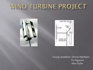
Wind Turbine Generators (WTGs) • Wind turbine components: • wind turbine runs at low speed (0.5 Hz) • mechanical drive train includes a gear box • converts low speed of turbine to high speed of generator • Mechanical speed regulation: • blade pitch angle control • each blade rotated about longitudinal axis • variable speed • stall control • no pitch actuators required • fixed speed • Types of generators • induction generator • synchronous generator • doubly fed induction generator • WTG ratings range from 25 kW to 3 MW
Typical WTG “Power Curve” • Fig below shows typical output versus wind speed characteristics of wind turbines: • The cut-in, rated and cut-out speeds shown are typical for utility-scale WTGs • Generally, WTGs are designed to work at maximum aerodynamic efficiency between cut-in and rated wind speed • For wind speeds higher than rated and lower than cut-out: • blade pitching or blade stalling is used to maintain loading within the equipment’s rating • WTGs shut down for wind speeds higher than cut-out speed to avoid excessive mechanical stress Percentage Rated Output cut-in rated cut-out wind speed (m/s)
Types of Wind Turbine Generator Technologies Presently four major types of WTG Technologies used: • Squirrel Cage Induction Generators driven by fixed-speed, stall-regulated wind turbines • Induction Generators with variable external rotor resistance driven by a variable-speed, pitch regulated wind turbines • Doubly-Fed Induction Generators driven by variable-speed, pitch regulated wind turbines • Synchronous or Induction Generators with full converter interface (back-to-back frequency converter), driven by variable-speed, pitch regulated wind turbines
Doubly Fed Induction Generator (DFIG) • Wound rotor induction generator with slip rings • Rotor is fed from a three-phase variable frequency source, thus allowing variablespeed operation • reduction of mechanical stress; higher overall efficiency, reduced acoustical noise • The variable frequency supply to rotor is attained through the use of two voltage-source converters linked via a capacitor Note: A more appropriate designation for this type of generator is: Doubly Fed Asynchronous Generator
Cbc Doubly Fed Induction Generator Used in Large Wind Farms DFIG Grid DC Link Rotor side converter Grid side converter Reactor Chopper
Control of Rotor-Side Converter • The converters handle ac quantities: • rotor-side converter carries slip frequency current • stator-side converter carries grid frequency current • Hence, they are controlled using vector-control techniques: • based on the concept of a rotating reference frame and projecting currents on such a reference • such projections referred to as d- and q-axis components • With a suitable choice of reference frame, AC quantities appear as DC quantities in the steady state cont’d
Control of Rotor-Side Converter cont'd • In flux-based rotating frames: • changes in the d-axis component of current will lead to reactive power changes • changes in the q-axis component will vary active power • This allows independent control of active and reactive power of the stator • Implemented through rotor-side converter control • An important aspect of the DFIG concept ! • Since rotor flux tracks the stator flux, air gap torque provides no damping of shaft oscillations • additional modulating signal has to be added
Protection System • Rotor current protection: • Limits current in the rotor side converter • If current rises above set value, a crowbar is activated • short-circuits the rotor winding at the slip rings with a static switch • the generator operates as a squirrel cage induction motor • Typically, the case when the voltage at the terminals of the generator decreases rapidly, for example during a fault in the grid • In order to avoid overspeeding of turbine, the speed reference for the pitch control is reduced simultaneously • increases pitch angle and reduces mechanical power
Protection System cont'd • Rotor speed protection: • disconnects WTG from the grid if speed of rotor is higher or lower than set levels for a predefined time • Over/under voltage protection: • disconnects WTG from the grid if voltage is above or below set values for a predefined time
Performance of DFIG • DFIGs have the ability to hold electrical torque constant • rapid fluctuations in mechanical power can be temporarily stored as kinetic energy • improves power quality! • Performance for large disturbances requires thorough analysis • may lead to separation of the unit • process may not be readily apparent from simplified dynamic simulations
Performance of DFIG cont'd • Large disturbances lead to large initial fault currents, both at the stator and rotor • will flow through rotor-side converter; voltage source converters are less tolerant of high currents • further, additional energy goes into charging the dc bus capacitor and dc bus voltage rises rapidly • crowbar may be activated • may lead to tripping of the unit • Need for a careful assessment and proper design of controls to improve capability to ride through faults
Examples of Fault Ride-Through Capability • Temporary reduction of active power: • Active Power is ramped down for a predefined time and then ramped up again to prefault value • This stabilizes wind turbine during the fault and reduces the current in the rotor converter • Disadvantage: rotor can speed up causing overspeed protection to trip turbine • handled by the pitch controller • Temporary reduction of active power with reactive power boosting: • Increases terminal voltage • Improves system stability
Wind Power Plants • Utility-scale wind power plants consist of several tens to hundreds of WTGs • Each unit with a pad-mounted transformer • Connected to transmission network through a medium-voltage collector network • A power transformer used to interface with the transmission grid • Depending on the application and type of WTG, shunt reactive power compensation may be added at one or more of the following locations: • WTG terminals • Collector system • Substation interfacing with the Transmission grid
Impact of the Variability of Wind Power Plant Output • Wind power plant output varies with wind resource • Cannot be dispatched like conventional power plants • System operators cannot control the rate of power decreases, i.e., ramp down due to falling wind speeds • For ramping up, some manufacturers provide the option of controlling rate of power increase • As wind power capacity within a control area increases, the variability of wind power can have a significant impact on: • the efficiency of unit commitment process, and • the reserve requirements to meet reliability performance standards • As an example, a study of a system with 35,000 MW peak demand estimated that the regulation reserves would increase by 36 MW when adding 3,300 MW of wind power
Reactive Power Compensation and Voltage Control Requirements • In areas with large amounts of wind generation, wind variability can have a significant impact on voltage profiles • may require switched capacitor banks and shunt reactors, and transformer tap changer control • Some wind power plants have the ability to control/regulate voltage at or near the point of interconnection to transmission grid • accomplished by installing separate devices such as SVCs and STATCOMS, • alternatively, external controller may be added for adjusting the power factor of each individual WTG until target voltage is achieved
Impact of Wind Power Plants on Power System Dynamic Performance • The dynamics of individual WTGs and the entire wind farms could have a significant impact on the stability of the bulk power system • “Rotor angle stability” is not an issue with wind power plants because most WTGs are asynchronous units • No equivalent concept of “rotor angle” or synchronizing and damping torques for such generators • Some studies have revealed that bulk power system “transient rotor-angle stability” is improved if wind power plants, as compared to conventional power plants with synchronous generators, are added at the same location • with WTGs, a smooth and non-oscillatory power delivery is re-established following a disturbance cont’d
Impact on System Dynamic Performance cont’d • Wind power plants could have a significant impact on “voltage stability” following a network fault • Induction generators absorb higher reactive power when voltage is low Even DFIGs may “crow-bar” during a fault, and act as an induction generator • Increased reactive power consumption can lead to voltage instability if the transmission grid is weak • Voltage stability related to characteristics of WTGs, as opposed to load characteristics • A short-term phenomenon • Adequate and fast control of reactive power and voltage required • Overall solution requires coordinated control of wind farms, including use of external compensators such as SVCs and STATCOMS cont’d
Impact on System Dynamic Performance cont’d • DFIGs and generators with full converter interface do not contribute to system inertia • May contribute to “frequency instability”, particularly in smaller power systems with high penetration of wind generation • Special controls needed to solve this problem • Present WTG designs do not contribute to primary frequency regulation • Some demonstration projects in Europe have illustrated the possibility of frequency regulation using WTGs • Requires more work and study before practical implementation • Detailed simulation studies using appropriate wind plant models essential for satisfactory integration of large wind farms into power grids
Impact on System Dynamic Performance cont’d A good source of reference addressing some of these issues is the CIGRE Technical Brochure on: “Modeling and Dynamic Behavior of Wind Generation As It Relates to Power System Control and Dynamic Performance” - Prepared by WG C4 - 601 of CIGRE Study Committee C4, January 2007
Modelling of Wind Farms • Wind field model describing wind speed • Wind turbine model • Model for internal grid of wind farm • For system studies aggregated representation is sufficient • a single WTG model to represent the farm or a sub-group of WTGs • Induction generator represented by a third order model • d and q axis rotor circuits and acceleration of rotor • Models for controls and protections --------------------- Some of the modeling details/data considered: - proprietary information by manufacturers Need to move towards the development of: - “standard models” for planning and operating studies
Grid Codes • In the past, wind power plants were allowed to trip off for nearby transmission faults and system disturbances • Due to the increase in wind power capacity, this is no longer appropriate • Transmission operators and reliability coordinators have begun to capture performance requirements for wind power plants in Grid Codes • The Grid Codes address, among other issues, • Fault tolerance and reactive power/voltage control requirements • In some cases, they also address • Ramp rate control and frequency response capability
Use of Multi-Terminal VSC-Based HVDC for Collector Network • An effective way to integrate large percentage of wind generation • Permits interconnection with main transmission network at relatively weak parts of the network • Provides good dynamic response and ability to comply with grid code requirements in the event of AC system faults • Results in smaller “footprint” • Growing interest in the application for interconnection of off-shore wind farms with the transmission network