Download
1 / 31
310 likes | 468 Vues
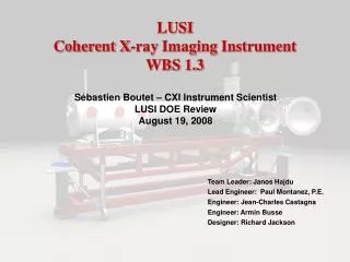
LUSI Coherent X-ray Imaging Instrument. Sébastien Boutet – CXI Instrument Scientist LCLS Facilities Advisory Committee Meeting June 17, 2008. Team Leader: Janos Hajdu Lead Engineer: Paul Montanez Designer: Jean-Charles Castagna Designer: Richard Jackson. Outline. Introduction

E N D
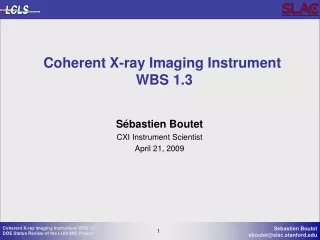
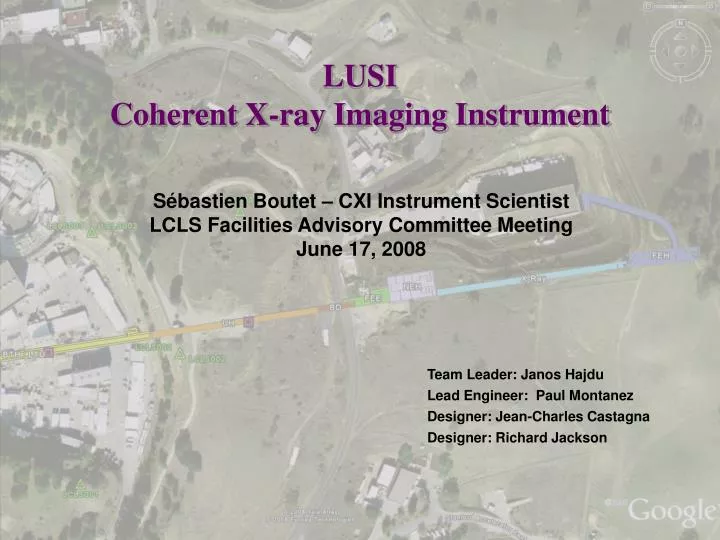
LUSICoherent X-ray Imaging Instrument Sébastien Boutet – CXI Instrument Scientist LCLS Facilities Advisory Committee Meeting June 17, 2008 Team Leader: Janos Hajdu Lead Engineer: Paul Montanez Designer: Jean-Charles Castagna Designer: Richard Jackson
Outline • Introduction • Instrument Overview • Key Components • KB Mirrors • Sample Environment • Summary
Coherent Diffractive Imaging of Biomolecules One pulse, one measurement Particle injection LCLS pulse Wavefront sensor or second detector Noisy diffraction pattern Combine 105-107 measurements into 3D dataset Gösta Huldt, Abraham Szöke, Janos Hajdu (J.Struct Biol, 2003 02-ERD-047)
CXI Instrument Location Near Experimental Hall X-ray Transport Tunnel XPP AMO (LCLS) CXI Endstation XCS Source to Sample distance : ~ 440 m Far Experimental Hall
Far Experimental Hall Control Room Lab Area High Energy Density Instrument X-ray Correlation Spectroscopy Instrument Coherent X-ray Imaging Instrument
X-ray Transport Optics & Diagnostics • Soft X-ray Offset Mirror System (SOMS) selects 800-2000 eV range for soft X-ray line • Hard X-ray Offset Mirror System (HOMS) selects 2-25 keV range. • HOMS periscope located just upstream of the Near Experimental Hall • 385 mm clear aperture mirrors >70% transmission at 2 keV and >98% at 8.3 keV
CXI Instrument Optics and Diagnostics (X-ray Transport Tunnel) 0.1 micron KB system Particle injector Diagnostics & Second Detector Ion Time of Flight LCLS Beam 1 micron focus KB system (not shown) Sample Chamber with raster stage Detector
CXI Kirkpatrick-Baez Mirrors • KB1 Mirror system Purpose • Produce a 1 micron focal spot at sample • Located ~8 meters upstream of sample • For samples smaller than 1 micron • KB0.1 Mirror system Purpose • Produce a 100 nm focal spot at sample • Located ~0.8 meters upstream of sample • For samples smaller than 50 nm • KB Mirror Requirements • >75% reflectivity over the widest energy range possible • At least up to 9keV • Accept 5 sigmas or more over the widest energy range possible • Match at least the angular acceptance of the Hard X-ray Offset Mirrors (HOMS) • Withstand full power of the LCLS beam without damage • Preserve coherence • Meet the Maréchal criterion at 8.3 keV, the highest fundamental energy • Ultra-High vacuum • < 10-9 Torr
Key Technical Choices • Coating material • Affects reflectivity • Determines maximum incidence angle • Damage issues with high Z materials • Incidence angle • Determines the energy range • Determines mirror length • Mirror length • How long can you make the mirrors and still polish them to the required accuracy?
Reflectivity of B4C at 3.4 mrad • 30 nm B4C • 3.4 mrad incidence • Low angle • Long mirrors • Or poor performance at low energies where the beam is larger • Reflective up to ~9 keV • Low Z material • Damage resistance
Reflectivity of B4C at 5 mrad • 30 nm B4C • 5 mrad incidence • Relatively short mirrors • Reflective up to ~6 keV • Not sufficient • Low Z material • Damage resistance
Reflectivity of Rh at 5 mrad • 40 nm Rh • 5 mrad incidence • Relatively short mirrors • Reflective up to ~12.5 keV • Absorption edge at 3 keV • High Z material • Possible damage issues
Reflectivity of Rh/B4C at 3.4 mrad • Bilayer • Top layer: 30 nm B4C • Bottom layer: 40 nm Rh • 5 mrad incidence • Relatively short mirrors • Reflective up to ~12.5 keV • Reflects off B4C only up to 6 keV • Removes the problem with the Rh edge at 3 keV • Peak reflectivity around 8.3 keV • No damage problems • B4C protects Rh at low energies
Acceptance of 350 mm long mirrors 5 sigma minimum target
Radiation Damage Issues • Calculations shown on plots assume normal incidence • Grazing incidence reduces dose • Lots of uncertainty in the calculations • Need to measure damage thresholds under LCLS conditions • Melting threshold is independent of incidence angle • Rh coating alone can only be used above 4 keV • Based on these uncertain calculations • Measurements may reveal Rh is safe below the critical angle • Other similar material (like Ru which has a higher melting temperature) could be used instead of Rh • Thermal fatigue threshold • Thermal cycling can lead to cracking • Depends on the mechanical properties of the material
Preferred Solution • Bilayer of Rh and B4C • 40 nm Rh • 30 nm B4C • Mirror usable length • 350 mm • 8.2 m and 7.8 m focal lengths • High damage threshold • 5 mrad maximum incidence angle • 4.94 mrad average incidence angle
Preserve the coherence of the beam Satisfy the Maréchal criterion at 8.3 keV >80% of incident intensity in the central peak at the focal plane hrms= rms height error over entire length of the mirror l=wavelength N=number of reflective optics (2 in this case) a=incidence angle At 8.3 keV hrms= 0.75 nm At 25 keV hrms= 0.25 nm Difficult roughness to achieve Nobody has ever done so on such large mirrors 0.56 nm achieved on 100 mm mirrors Figure Error
Wide range of incidence angles due to short focal length and high curvature of the surface 3-5 mrad Two reflective surfaces Phase shifts effect on focus? Two beams at focus? Simulations are required Issues with bilayer for 0.1 micron KB
Proposed Solution • Rh/B4C Bilayer for 1 micron KB • 40 nm Rh • 30 nm B4C • 350 mm usable length • 8.2 m and 7.8 m focal length • 5 mrad incidence angle • 0.75 nm rms height error • MUST get early access to soft X-ray beam of LCLS • Measure the damage threshold of Rh at grazing incidence • Experimental determination of feasibility of using single layer of Rh for 0.1 micron KB • If Rh or Ru can survive the beam • Single layer Rh for 0.1 micron KB • 2-12.5 keV range • If Rh or Ru cannot survive the beam • Single layer B4C for 0.1 micron KB • Loss of functionality with reduced energy range • 4-9 keV
CXI 0.1 micron KB • 100 nm focus is required for imaging small particles • Focal length • First mirror • 900 mm • Second mirror • 500 mm • Focus • 68 x 120 nm spot • Requires reentrant KB design • Closest point of approach to interaction region • 300 mm • Final sample chamber design cannot occur until we have a final KB design
Sample Environment - Fixed Targets • Sample Environment Requirements • Vacuum better than 10-7 torr • Rapid access • Multiple apertures • Aperture Purpose • Clean beam halo • Remove slit scatter from upstream slits • Aperture Requirements • Apodized edges • Positional resolution and repeatability : <1 µm • Easily replaced if destroyed by the beam • Likely made of etched Si wedges • Multiple samples held on multiple grids • Large area for hit-and-miss with small samples • Sample pitch and yaw • High resolution telescope for sample viewing Apertures Sample
Sample Environment - Injected Particles • Sample stage can be translated and used as an aperture • Utilize the same setup for fixed samples and particle injection • Particle beam comes in from the top • Particle beam aperture • Particle beam diagnostics • Charge detectors Particle Beam Aperture
CXI Detector Stage • Detector Stage Purpose • Center the detector hole on the direct beam • Position the detector at the appropriate distance from the interaction region • Detector Stage Requirements • Range along the beam : 50-2600 mm • Non-continuous • Vacuum better than 10-7 torr • Diagnostics behind the detector for alignment • Valve to isolate the detector vacuum Sample Detector Detector
Temporary Chamber • Build a first chamber decoupled from the KB0.1 system • Full chamber functionality • Fixed targets • Injected particles • Ion time-of-flight • Compatible with detector stage • May not be compatible with KB0.1 system • Reuse the interior components • Build a second chamber • Temporary stand • May not be reusable with KB0.1 • Pros • Ready for beam sooner • Can learn from the first chamber to design a better final chamber • Cons • Costs more $$$$
Summary • Proposed solution for 1 micron KB • Use Rh/B4C bilayer • Measure damage thresholds at LCLS to determine solution for 0.1 micron KB • Bilayer will likely not work • Could possibly use heavy metal coating alone • Design and fabrication can proceed with temporary chamber decoupled from KB systems • Early operations with only 1 micron KB • Full functionality included in temporary chamber