Active Filters
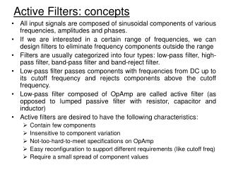
Active Filters. Introduction. Filtering : most common linear time-invariant (LTI) signal processing function – selecting the signal bandwidth of interest (in reality neither linear nor time-invariant)… Categories : continuous time (CT), discrete time (DT)

Active Filters
E N D
Presentation Transcript
Introduction Filtering: most common linear time-invariant (LTI) signal processing function – selecting the signal bandwidth of interest (in reality neither linear nor time-invariant)… Categories: continuous time (CT), discrete time (DT) analog filter, digital filter (will focus on CT analog filters for this course) Frequency domain:low-pass (LP), high-pass (HP), band-pass (BP)… Time domain: impulse response, FIR, IIR…
Simple RC Filter Continuous-time, 1st-order, one real pole, low-pass
Simple RC Filter Frequency response Impulse response
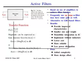
General Filter Specs • Ideal LPF: • Non-causal • Infinite complexity • More realistic: • Magnitude response • ωp, ωs, αp, and αs • Phase response
Example: 2nd-order VTF • Continuous-time • Where are the poles? (complex conjugate poles for maximum flatness) • Low-pass, high-pass, or band-pass?
Passive RLC Filter • No active component (low power) • Inductors are bulky and expensive to realize in IC’s • Values of R, L, and C will not track each other
Active OP-RC Filter • It’s active • Inductor-less • Area efficient • Values of R’s and C’s and their time co.’s won’t track each other – may lead to RC time constant variations of as high as 20% • RC time constant enters the VTF in product form – can be tuned for accuracy Assuming ideal op amps,
Continuous-Time Integrator Assuming ideal op amp,
Cascade Filter Design For a real-coefficient H(s): 2nd-order 1st-order Biquad: The leading minus sign in Hbq(s) is only for convenience
Signal Flow Graph (SFG) for Biquad Note: the partition of the biquadratic VTF is not unique
Alternative SFG for Biquad Recast Hbq(s):
Cascade Filter Design For a real-coefficient H(s): 2nd-order 1st-order • Order of cascade determines the signal dynamic range • Optimized using engineering rule of thumb or thru simulation
Biquad Cascade Filter Design • Most flexible arrangement of cascade filter design • Allow independent, non-interacting control of (ω0, Q) for pole pairs • Easy design • Components need to be scaled for maximum DR and minimum component spread • Pass-band sensitivity to capacitance variation is finite → Ladder filter can achieve zero sensitivity
Typical Active Multi-Stage Filters Initial component values may not be optimal...
Freq. Response of Internal Nodes • Internal signal swings need to be large to max SNR • But not too large such that op amps saturate (producing distortion)
DR Scaling of ith Integrator (Vi) • First find out the peak value of Vi(ω), mostly done with simulation • Then find out the ratio ki = Vi,peak/Vo,max • Multiply all capacitors connecting at Vi by ki: Fi → Fi*ki, Sij → Sij*ki, … • Divide all resistors connecting at Vi by ki: Fi → Fi*ki, Sij → Sij*ki, … • Repeat for all internal nodes…
After DR Scaling Max internal signal swings all line up to Vo,max
Scaling for Min. Component Spread • Find out the smallest cap/res connected to Xi – the summing node of Ai • determine the optimum scaling factor mi to minimize spread • Multiply all capacitors connected to Xi by mi: Fi → Fi*mi, Sji → Sji*mi, … • Divide all resistors connected to Xi by mi: Fi → Fi*mi, Sji → Sji*mi, … • Repeat for all integrators…
Scaling of Active Filter • DR and min spread scaling do not take op-amp loading into account – lots of work if individual op amps are sized to meet the settling time constraint • Upon the completion of scaling, simulation needs to be performed on the resulting filter to find out the overall SNR • If SNR is lower than the spec, capacitors and op amps need to be scaled up and resistors scaled down to meet the SNR spec (think about how integrated output noise behaves)
Motivation • Cascade filter design • Sensitive to component variations, especially high-Q poles • Ladder filter design • Achieves zero sensitivity to component variations • Discrete CT LC filters with very high-Q poles are built with ladder structures over the years
Ladder Filter Reactance two-port • Doubly terminated reactance two-port network • Delivers the optimum power matching in the passband • ∂|Vout|/∂Zi = 0 for all L’s and C’s → low sensitivity
State Space of Ladder Filter Pick –V1, -I2, V3 as the state variables for synthesis
CT OP-RC Ladder Filter • Three free state variables → three op amps • A.k.a the leapfrog ladder structure
OP-RC Ladder Filter w/ Derivatives • Derivative input paths implemented with capacitors
Tow-Thomas Biquad • Low sensitivity • Non-interactive • tuning property [1] P. E. Fleischer and J. Tow, "Design formulas for biquad active filters using three operational amplifiers,“ Proceedings of the IEEE, vol. 61, pp. 662-3, issue 5, 1973.
Design Equations for Tow-Thomas Note: C1, C2, k1, k2, R8 are free parameters
Sallen-Key LPF • OP-RC active filters are ideally insensitive to bottom-plate stray caps • Sallen-Key is sensitive to bottom-plate parasitics at node A and B
Sallen-Key BPF Still sensitive to parasitic capacitance at node A and B
MOSFET Resistor • MOSFET in triode region is a variable resistor • Compact, low parasitics compared to large-value resistors
MOSFET Resistor But the large-signal response is quite nonlinear
A Linear (Diff.) MOSFET Resistor MOSFET resistor is linear when driven by balanced differential signals!
Rudell VGA + Mixer • M9-M15 comprise • the CMFB circuit • Gain adjustment • by varying IGain [2] J. C. Rudell et al., “A 1.9-GHz wide-band IF double conversion CMOS receiver for cordless telephone applications,” IEEE Journal of Solid-State Circuits, vol. 32, pp. 2071-88, issue 12, 1997.
MOSFET-C Integrator = • Sources of M1 and M2 are ideally always equal-potential • Fully differential circuit rejects the 2nd-order harmonic (and all even-order distortions) • Triode resistance significantly depends on process (threshold, mobility, etc.), temperature, and VDD→ Filter response needs tuning