Download
1 / 53
820 likes | 2.06k Vues
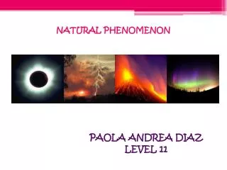
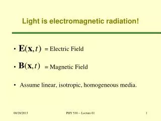
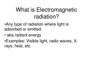
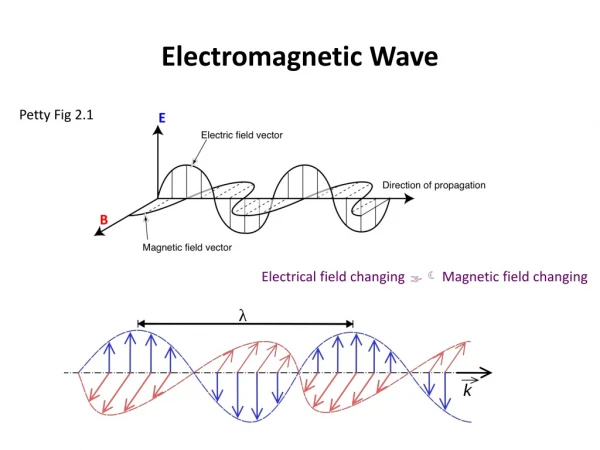
Electromagnetic Radiation. Electromagnetic radiation is a natural phenomenon that moves as a wave. An electromagnetic wave is a set of two transverse waves that move perpendicular to each other: One wave is an electric field The other wave is a magnetic field

E N D
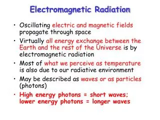
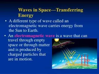
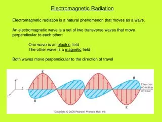
Electromagnetic Radiation Electromagnetic radiation is a natural phenomenon that moves as a wave. An electromagnetic wave is a set of two transverse waves that move perpendicular to each other: One wave is an electric field The other wave is a magnetic field Both waves move perpendicular to the direction of travel
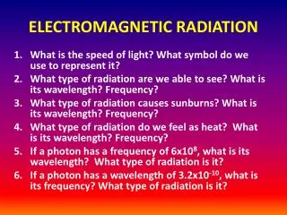
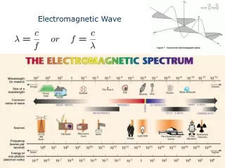
What all types of EM radiation have in common: • are all made up of electric and magnetic fields • all travel at the same speed in a given medium • The types of EM radiation differ in that they: • have different wavelengths • have different frequencies • have different energies • Although all types of electromagnetic radiation travel at the same wave speed through a given medium, the wave speed will change if the medium is changed. • Wave speeds of EM radiation • c (air/vacuum) = 3.00 x 10⁸ m/s • v (water) = 2.26 x 10⁸ m/s • v (glass) = 2.00 x 10⁸ m/s
What is the wavelength of a 29.75 x 10⁹ Hz radar signal as it passes through air? If the Sun were disappear or somehow radically change its output, how long would it take for us on Earth to learn about it? The Sun is 93 million miles away and 1 in = 2.54 cm
Refraction When light passes from one medium to another, it is going to travel at a different speed, If it hits the boundary between the two mediums at an angle other than perpendicular, the light ray is going to change direction. This phenomenon is called refraction. When light travels from a less dense medium (air) to a more dense medium (water), light bends toward the normal. Angle of refraction is smaller than the angle of incidence.
When light travels from a more dense medium (water) to a less dense medium (air), light bends away from the normal. Angle of refraction is larger than the angle of incidence. The amount of bending is determined by each substance’s index of refraction (n). n = c / v n = index of refraction (ratio…no units) c = speed of light in vacuum (m/s) v = speed of light in medium (m/s)
Refraction is responsible for many optical illusions that we experience.
Snell’s Law The amount of refraction can be calculated using Snell’s Law (Law of Refraction) n1 sin θ1 = n2 sin θ2 Θ1 = angle of incidence Θ2 = angle of refraction n1 and n2 = respective indices of refraction
Light traveling in air strikes a flat piece of uniformly thick glass at an incident angle of 60. If the index of refraction of the glass is 1.50, what is the angle of refraction in the glass and the angle at which the ray emerges from the glass?
Assuming that the equilateral prism has index of refraction of 1.58, at what angle does the light leave the prism?
Total Internal Reflection When light passes from a more dense medium to a less dense medium, there is a point where light can no longer bend away from the normal. The light bends and runs parallel to the surface. At that point, the light doesn’t bend…it reflects back and remains in the incident medium. This phenomenon is total internal reflection.
Fiber optic cables transmit signals because of total internal reflection.
The angle at which it occurs is called the critical angle (θc). Applying Snell’s Law… n1 sin θ1 = n2 sin θ2 n1 sin θc = n2 sin 90 sin θc = n2 (1) / n1 sin θc = n2 / n1
Lenses A lens uses the refraction of light to create an image of an object A converging lens bends parallel light rays toward a common point known as the focal point. The distance from the lens to the focal point is called the focal length (positive).
RayDiagrams Converging Lenses produce Real Images (can be seen on screen)
Lens Equation Other Equations M = - di / do = hi / ho P (diopters) = 1 / f 1 / f = 1 / do + 1 / di
A lens with a focal length of 20 cm focuses the light rays from an 5.0-cm object that is 35 cm away to create an image on a screen. • How far is the image from the lens? • What is the magnification of the lens? • What is the height of the image? • What is the power of the lens? • Describe the image.
If the object is placed within the focal length, the rays do not converge on the other side of the lens. They are extended back to a point where a virtual image is formed
Two – Lens Systems Basic Rules: Image for 1st lens becomes object for 2nd lens Overall magnification is product of individual magnifications
Two converging lenses, A and B with focal lengths fa = 20.0 cm and fb = 25.0 cm, are placed 80.0 cm apart. An object is placed 60.0 cm in front of the first lens. Determine (a) the position, and (b) the magnification, of the final image formed by the two lenses.
How We See Things We see objects because light travels from an object through the lens in the front of our eye creating a real image on our retina. • Objects that we see are either: • Sources of light (sun, light bulbs, candles) • Reflectors of light (all other visible objects that don’t produce their own light)
Sources of Light • Three Basic Patterns: • Regular Light (incoherent and non-collimated) • Collimated Light (all light rays travel parallel) • Coherent Light (all light rays parallel and in phase)
Reflection Most objects we see do not give off their own light; rather, they reflect light from a source. • Two Types of Surface Reflection • Diffuse reflection (rays reflected in all directions from a rough surface) • Specular reflection (rays reflected in one direction from smooth surface
Spherical Mirrors Spherical mirrors focus incoming light rays on a specific point called the focal point. The law of reflection remains true for spherical mirrors. Mirrors that reflect light rays back in a converging pattern are called concave mirrors. Spherical mirrors have center of curvature (C) in addition to focal point (f).
Mirror Equation Other Equations M = - di / do = hi / ho C = 2f 1 / f = 1 / do + 1 / di
Lens Summary http://paws.kettering.edu/~drussell/Demos/RayTrace/Lenses.html
Mirror Summary http://paws.kettering.edu/~drussell/Demos/RayTrace/Mirrors.html
Interference and Diffraction When waves encounters certain obstacles, they appears to bend in the “shadow region” of the barrier. This phenomenon is known as diffraction. This is true of all waves. It is especially visible with coherent light (laser -- crests are in phase), but it is also present with monochromatic light. This could NOT be explained with Netwon’s theory that light was a particle. Particles would not drift into the shadow region.
In order to explain this phenomenon, Christiaan Huygens proposed that light is a wave made up of smaller “wavelets”. Each wavelet moves out from a point on the original wave (AB). Dutch Physicist and Author 1629 - 1695 The tangent connecting all the wavelets makes up the new wave front (CD) which forms a short time after AB.
About 100 years later, Thomas Young experimented with diffraction through a double-slit. What actually was observed was this pattern. If light behaved like a particle, the pattern would look like this: British Physicist 1773 – 1829 Young’s work provided evidence supporting the wave theory of light.
When coherent light hits barrier with two slits, a diffraction pattern is produced by each slit. Diffracted waves interfere with each other on other side to produce interference bands alternating bright and dark.
The center bright line is formed by waves from both slits that travel the same distance and are in phase. These waves constructively interfere.
Other instances of constructive interference produce bright lines on either side of center Difference: At this angle, lower wave travels one wavelength farther than top wave. Distance between lines: First bright line away from center at angle θ tan θ = x / L Distance depends on wavelength of light and the distance between slits sin θ =λ / d When L is large relative to x, tan θ = sin θ x / L = m λ / d Two – Slit Interference Formula x = m λ L / d m = 0, 1, 2,… for constructive inter. (bright) m = 0.5, 1.5, 2.5… for destructive inter. (dark)
A screen containing two slits 0.100 mm apart is 1.20 m from the viewing screen. Light of wavelength λ= 500 nm falls on the slits from a distant source. How far apart will adjacent bright interference bands be on the screen?
Single-slit diffraction Further studies done with single-slit barriers provided evidence of light acting as a wave. Single-slit diffraction creates pattern with central bright fringe and secondary fringes that are much dimmer. Bright central fringe caused by light directly hitting screen.
At angle θ, ray at top of slit is exactly one wavelength longer than ray at bottom of slit. It destructively interferes with ray halfway down because they will be ½ λ out of phase when they hit the screen.
Other dark regions occur at other angles that have corresponding waves that destructively interfere. D = width of slit (m) Single – Slit Interference Formula Dsin θ = mλ m = 1, 2, 3,… for destructive inter. (dark)
Secondary bright fringe produced at angle θ where top ray is 3/2 λ longer than bottom ray. Ray with ½ λ extra will cancel out ray with 1 λ extra. What is left is 3/2 λ ray which makes bright fringe. Single – Slit Interference Formula Dsin θ = mλ m = 1.5, 2.5,… for constructive inter. (bright)
Light of wavelength 750 nm passes through a slit 1.0 x 10⁻³ mm wide. Assuming the screen is 20 cm away, how wide is the central maximum (bright fringe) in (a) degrees and (b) centimeters,?
Diffraction Grating Diffraction gratings use numerous parallel slits (10,000 per cm) to separate incident light into its various colors. • Produced by mixture of 700 nm light and 400 nm light • Produced by white light Various colors of incident light produce groups of lines at each order. Functions like two-slit diffraction, although pattern is sharper because numerous slits are producing the pattern Diffraction Grating Formula dsin θ = mλ m = 0, 1, 2,… for constructive inter. (bright) d = distance between slits
Determine the angular positions of the first- and second-order maxima for light of wavelength 400 nm and 700 nm incident on a grating containing 10,000 lines/cm.
Dispersion Refraction deals with the “Big Picture”: We treated incident light as monochromatic (all one wavelength) We treated the refractive medium as having one refractive index Dispersion deals with “The Details” Most light has multiple wavelenghts Each wavelength actually has its own refractive index
Not only does the index of refraction depend on the substance, but it also depends on the wavelength. Example: Red light in quartz n = 1.55 v = 1.94 x 10⁸ m/s Violet light in quartz n = 1.56 v = 1.92 x 10⁸ m/s So, violet light travels slower and bends more than red
Rainbows demonstrate dispersion when raindrops in front of you are illuminated by sunlight behind you. Spherical shape causes sunlight to disperse and then reflect back. Because red light bends less than violet light, the red light is seen higher in the sky than the violet light
Thin- Film Interference Look familiar?
Thin-film interference occurs when incident light is transmitted through a medium that is similar in width to the wavelength of light. Some of the light reflects off of front surface. Some reflects off of back. When two waves reaching the eye are in phase, they produce constructive interference. When they are out of phase, they produce darkness. When ray moves into film, it has a different wavelength λn = λ/n