Download
1 / 36
800 likes | 1.71k Vues
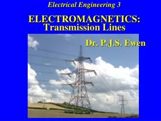
Electrical Engineering 3 ELECTROMAGNETICS: Transmission Lines Dr. P.J.S. Ewen. ELECTROMAGNETICS – TRANSMISSION LINES Arrangements are same as for Prof. Murray's part of the course: Lectures: Tuesdays 9.00 – 9.50 LT 2

E N D
Electrical Engineering 3ELECTROMAGNETICS: Transmission Lines Dr. P.J.S. Ewen
ELECTROMAGNETICS – TRANSMISSION LINES Arrangements are same as for Prof. Murray's part of the course: Lectures: Tuesdays 9.00 – 9.50 LT 2 Thursdays 15.10 – 16.00 LT 2 Fridays 15.10 – 16.00 LT 2 Tutorials: Tuesdays 15.10 – 16.00 CR10
SYLLABUS Part 1 - Introduction and Basics Lecture Topics 1. General definition Practical definition Types of transmission line: TE, TM, TEM modes TEM wave equation - equivalent circuit approach 2. The "Telegrapher's Equations" Solution for lossless transmission lines: F(t±x/v) Simplest case of F(t±x/v) 3. Direction of travel of cos/sin (ωt ±βx) waves Phase velocity of a wave on a transmission line General transmission line: attenuation
Part 2 - Characteristic Impedance and Reflections Lecture Topics 4. Current and voltage on a transmission line: Characteristic impedance, ZO Characteristic impedance of lossless lines Characteristic impedance of general lines Infinitely long transmission lines Reflections on transmission lines 5. Transmission line with change of ZO: voltage reflection coefficient Voltage reflection coefficient at an arbitrary distance l from the load ZL 6. Impedances of terminated lines Voltage Standing Wave Ratio (VSWR) Voltage Standing Wave measurement
Part 3 - The Smith Chart and its Applications Lecture Topics 7. Introduction to the Smith Chart Principle of operation Construction of the Smith Chart Key points on the Smith Chart 8. Using Smith Chart with load and line combinations Smith Chart and general transmission lines Effect of variation in frequency Smith Chart and VSWR Using the Smith Chart and VSWR to find ZL 9. Adding components using a Smith Chart Matching with Smith Chart and series components Admittance using a Smith Chart Single Stub Matching
Lecture 1 • Define what is meant by a transmission line • Look at different types of line Part 1 - Introduction and Basics • Lecture 2 • Equations governing the current and voltage on a transmission line • Solution to these equations for the simplest case – current and voltage propagate as waves I or V • Lecture 3 • Properties of waves on a transmission line • General transmission line - attenuation Distance, x
Lecture 4 • Characteristic impedance, ZO • Reflections on transmission lines − Reflected voltage wave −Forward voltagewave Part 2 - Characteristic Impedance and Reflections -x +x • Lecture 5 • Voltage reflection coefficient Vr / Vi = r • Lecture 6 • Impedances of terminated lines Zin≠ Zo + ZL Zo ZL
Part 3 - The Smith Chart and its Applications • Lecture 7 • Introduction to the Smith Chart • Principle of operation • Lecture 8 • Using the Smith Chart to solve various transmission line problems • Lecture 9 • Designing matching circuits using the Smith Chart Zo Matching circuit or network ZL Zo Forward power only Source Load Transmission line (Zo)
Recommended Text: J.D. Kraus and D.A. Fleisch, "Electromagnetics with Applications", McGraw-Hill. This is a comprehensive text covering most of the material in the Electromagnetics course. It is also a recommended text for the 4th year course on RF Engineering.
Handout on Transmission Lines • Lecture notes for all the lectures • Lecture summaries • Tutorial sheets A - D • Lecture examples • Formula sheet (same as for exam) • Tutorial solutions will be distributed at tutorials (and are available on LEARN).
The PowerPoint "slides" are available on the web … … go to the “Electromagnetics 3: Signal Transmission” page on Learn and click on “Teaching materials – Transmission Lines”
Under certain circumstances all these can be regarded as transmission lines: Co-ax cable Pair of wires PCB tracks IC interconnects
GENERAL DEFINITION A transmission line can be defined as a device for propagating or guiding energy from one point to another. The propagation of energy is for one of two general reasons: 1. Power transfer (e.g. for lighting, heating, performing work) - examples are mains electricity, microwave guides in a microwave oven, a fibre-optic illuminator.
2. Information transfer – examples are telephone, radio, and fibre-optic links (in each case the energy propagating down the transmission line is modulated in some way).
CE amplifier circuit Because signals cannot travel faster than the speed of light, if the voltage at A changes it will take a finite time for the information to reach B – during that time the voltages at A and B will be different.
Example 1.1 - Voltage and phase difference along a transmission line A remote step-down transformer (B) is connected by a transmission line 600 km long to a generating station (A) supplying 50 Hz AC. At time t = 0 the generator is switched into the line and the voltage at the generator is at its maximum, Vm. What are the voltage and phase differences between the ends of the line at the instant power reaches the transformer? Generating station Transformer 600 km
Generator Transformer VA VB
Example 1.2 - Phase difference between the ends of a cable. Determine the phase difference between the ends of: (a) a 10m length of mains cable for a 50Hz electricity supply (b) a 10m length of coaxial cable carrying a 750MHz TV signal λ N.B. one wavelength corresponds to one complete cycle or wave, and hence to a phase change of 360º or 2π radians. So the phase change over a distance l is just 360ºl / λ (or 2πl / λ radians)
We have to treat a conducting system as a transmission line if the wavelength, , of the signal propagating down the line is less than or comparable with the length, l , of the line: l PRACTICAL DEFINITION Associated with transmission lines there may be: • Propagation losses • Distortion • Interference due to reflection at the load • Time delays • Phase changes
Cross section 2-wire line (dc) Some different types of transmission lines: 2-wire line (ac) Coaxial line (dc, ac, rf) Microstrip line (rf) Rectangular waveguide (rf) Optical fibre (light) Radio link with antennas
Microstrip line cross section dielectric conductors conductor dielectric
Waveguide rectangular waveguides cross section
The energy propagating down a transmission line propagates as an electromagnetic wave. Different patterns of E and H fields are possible for these waves. Each pattern constitutes a “mode of propagation”: MODES OF PROPAGATION
These modes fall into two categories: TE – TRANSVERSE ELECTRIC TM –TRANSVERSE MAGNETIC MODES OF PROPAGATION TEM Modes: In the special case where E and H are both transverse (i.e. at right angles) to the direction of energy flow, the mode is termed TEM. E and H will also be at right angles to each other. TEM – TRANSVERSE ELECTROMAGNETIC TE mode
The kinds of mode that can propagate down a line depend on the geometry and materials of the line. • Transmission lines can be classified into 2 groups according to the type of mode that normally propagates down them. 1. LINES PROPAGATING TEM MODES: There is no E or H field in the direction of propagation. • twin-wire, coaxial, stripline and (approximately) microstrip lines are in this group. 2. LINES PROPAGATING TE OR TM MODES: E or H have components in the direction of energy flow. • waveguides and optical fibres are in this group.
The details of wave propagation on a transmission line can be deduced from Maxwell's Equations. However, TEM guided waves on a transmission line can also be analysed using a lumped equivalent circuit approach. TEM WAVE EQUATION EQUIVALENT CIRCUIT APPROACH TO TRANSMISSION LINE ANALYSIS Real transmission lines have associated with them: a resistance per unit length, R a capacitance per unit length, C an inductance per unit length, L and a (leakage) conductance per unit length, G. (Note that R represents the resistance of both conductors in the line.)
for wires in air and with d >> a: a = wire radius d = wire spacing εo = permittivity of free space μo = permeability of free space FOR PARALLEL WIRES: FOR COAXIAL CABLE: a = radius of inner conductor b = inner radius of outer conductor ε= permittivity of dielectric in cable μ = permeability of dielectric in cable
The details of wave propagation on a transmission line can be deduced from Maxwell's Equations. However, TEM guided waves on a transmission line can also be analysed using a lumped equivalent circuit approach. TEM WAVE EQUATION EQUIVALENT CIRCUIT APPROACH TO TRANSMISSION LINE ANALYSIS Real transmission lines have associated with them: a resistance per unit length, R a capacitance per unit length, C an inductance per unit length, L and a (leakage) conductance per unit length, G. (Note that R represents the resistance of both conductors in the line.)
LΔx RΔx GΔx CΔx The existence of an inductance, capacitance, resistance and conductance (per unit length) allows us to represent the transmission line by an equivalent circuit in which each infinitessimal length of transmission line is represented by the same combination of 4 components: EQUIVALENT CIRCUIT FOR A TRANSMISSION LINE Δx To make up the whole line, repeat the equivalent circuit a sufficient number of times.
LDx RDx GDx CDx Dx PRIMARY LINE CONSTANTS C = capacitance per unit length (F/m) L = inductance per unit length (H/m) R = resistance per unit length (W/m) G = conductance per unit length (S/m) Note:- • R, C, L and G are all expressed per unit length • R & G should be small for a good transmission line. • If R = 0 and G = 0, the line is termed “lossless”.
Example 1.3 - Impedance of an infinite lossless transmission line. Determine an expression for the impedance of an infinite, lossless transmission line.
PRACTICAL DEFINITION - Transmission line analysis must be used when the wavelength, , of the energy propagating down the line is less than or comparable with the length, l , of the line: • l • Definition of TE, TM & TEM modes − twin-wire, coaxial and strip lines only propagate TEM modes. • Transmission lines have capacitance, inductance and resistances associated with them and can be represented by an equivalent circuit. Summary
LDx RDx GDx CDx Dx • C, L, R and G are the primary line constants and are all expressed PER UNIT LENGTH • For a LOSSLESS LINE, R = 0 and G = 0