Download
1 / 11
120 likes | 259 Vues
LEAKAGE OF GAS THROUGH CAPROCKS: HEADSPACE GAS EVIDENCE FROM THE NORWEGIAN AND UK NORTH SEA. Selegha Abrakasa Andy Aplin Newcastle University. Potential Leakage Mechanisms. Along faults. Along fractures resulting from tectonic stress or high pore pressures.

E N D
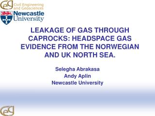
LEAKAGE OF GAS THROUGH CAPROCKS: HEADSPACE GAS EVIDENCE FROM THE NORWEGIAN AND UK NORTH SEA. Selegha Abrakasa Andy Aplin Newcastle University
Potential Leakage Mechanisms Along faults Along fractures resulting from tectonic stress or high pore pressures Pore system after capillary failure
STUDY SITES • 48 wells from 39 fields representing: • Reservoir depth range ~ 2700m – 3800m • Variety of pore pressure regimes: hydrostatic to fracture pressure • Variety of structural settings: diapiric, tilted/rotated fault blocks • Oil, gas and oil + gas accumulations
Headspace Gas • Commonly available • Variable quality • Can readily differentiate thermogenic and biogenic gas • Do profiles suggest flowpaths and leakage mechanisms? a) ppm of C1-C5 b) δ13C c) iC4/nC4 Cuttings from shale shaker in cans (canned cuttings) Gas sample in headspace collected and analysed by gas chromatography
SUMMARY STATISTICS: THERMOGENIC GAS ANOMALIES No. OF WELLS HEIGHT OF WET GAS ANOMALY ABOVE RESERVOIR (m)
Pore Pressure & Fracturing λ = Pore pressure / Lithostatic pressureRisk of mechanical failure increases at l ~ 0.8 Pressure Lithostatic Fracture Hydrostatic Pp Depth Lp
PRESENCE OF THERMOGENIC GAS IN CAPROCK NOT RELATED TO PORE PRESSURE
GASPROFILES:VIDGIS (34/7-29S) Res.@2705 Draupne Fm. Sst.
SHETLAND LI/CLY/SST CROMER KNOLL GP LI/SSTONE SST SST/ CLST VIKING CLST/ SLST/ SST FANGST BAT GP COAL UNIT GAS PROFILE: TYRIHANS 6407 / 1 - 3 1,300 m “HC shows in early Cret.”
SUMMARY & CONCLUSIONS • 39 N Sea fields: wide range of structural and pore pressure regimes • Almost all reservoir caprocks contain thermogenic gas; in this context they are leaking on geological timescales • 70% of reservoirs show thermogenic gas anomalies over 500m; 40% ≥ 1000m • 10% percent of leaking reservoirs had high potential for pressure induced fracture (λ = 0.8) • Are the majority of reservoirs leaking via capillary failure through pores? • Or: are we observing water flow? • Next: numerical analysis of profiles: timing, rates, mechanisms