Download
1 / 21
210 likes | 413 Vues
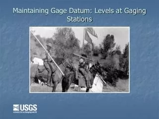
Maintaining Gage Datum: Levels at Gaging Stations. A visit to Pacific Creek at Moran, WY. The gage is referenced to a wire-weight gage attached to the upstream left bank side of the bridge. There are several brass caps or reference marks located around the gage. Plan View of Gage Site.

E N D
A visit to Pacific Creek at Moran, WY The gage is referenced to a wire-weight gage attached to the upstream left bank side of the bridge. There are several brass caps or reference marks located around the gage.
Reference Marks • Should have at least three stable RMs • They should be independent of each other • At least one should be located above the maximum potential flood stage
Preparation for a level circuit • Two-peg test the instrument to verify the collimation error is within |0.003| ft/100. Enter the results in the two-peg test log • Be sure to run tests on both the optical and digital systems of the instrument • With a steel tape determine that the enamel sections on the Philadelphia or Chicago rod read within 0.002 ft
Preparation for a level circuit (cont.) • Locate the initial or reference bench mark and the other reference marks or brass caps, clear debris away • Determine where you are going to set up for each shot • Level the instrument and begin by noting the time and initial elevation
Take a backsight on the origin (given elevation) to establish the initial elevation or height of the instrument (HI) for the level. North Fork Teton River near Teton, ID
Then take Foresights (FS) to objects [RMs, RPs, gages, WS etc.] to determine the first elevations. Establish an independent turning point (TP) by taking a FS on a stable object that is not included in the level circuit. North Fork Teton River near Teton, ID
Move and level the instrument. Take a BS to the established TP to determine a second HI. Take FS’s to the same objects to obtain the second elevations. The final FS should be taken on the original RM. North Fork Teton River near Teton, ID
Two criteria for a valid level circuit:Compute closure error of circuit [given elevation of origin minus final elevation of origin]. Closure must be less than or equal to |0.003*√n| where n is number of instrument setups. Distribute closure error to all HIs of level circuit.Compute difference between First and Second elevations for each object of level circuit. Difference in elevations must be less than or equal to |0.005| ft.
Key Points to Anticipate • Try to balance the distances from the instrument to all objects of level circuit • Obtain 2 shots on the water surface from different HIs and read the recorder, also noting the time of day • Shoot the bottom of the wire-weight while near the water surface • Turn on a stable object and shoot items in the reverse order to the point of beginning
To Conclude the Level Circuit • Verify that the circuit meets OSW criteria. • Field check level notes • Adjust gages if they differ from levels by |0.015| or more. • Write up the reason for and the findings of the level circuit on the note sheet • Have the level notes checked a second time. • Update the station description, level summary sheet, station history and SIMS • Update the office files
Back sheet Front sheet
Frequency of Levels OSW Memo 90.10 is the current guidance – (New levels T&M clarifies 90.10): • As a station is started, levels should be run every year for 3 years. • Levels at streamflow gaging stations should be run at least every 3 years. • If, after at least 5 sets of levels over a period of at least 10 years, the gaging station is shown to be stable, a lesser frequency of levels may be adopted.
Frequency of Levels (cont.) • If stability is shown to exist, levels should be run at least every: - 5 years at regular gaging stations. - 3 years at crest-stage stations. • Levels can always be run more frequently. • As a station is discontinued, a level circuit should be run. • A good routine would be to survey at least 1/3 of the levels each year.
Levels at Gaging Stations For more information: • Procedures for Running Levels at Gaging Stations, T. A. Kenney, Techniques and Methods 3-A19 • Levels at Streamflow Gaging Stations, E.J. Kennedy, TWRI, Book 3, Ch. A19 • Levels at Streamflow Gaging Stations A CD-ROM Training Class, K. Michael Nolan, Nathan Jacobson, Robert Erickson, and Stanley Landon • OSW Memo 90.10 (levels frequency) • OSW Memo 93.12 (side shots)