Download
1 / 42
420 likes | 440 Vues
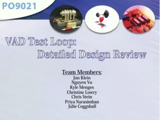
VAD Test Loop: Detailed Design Review. Team Members: Jon Klein Nguyen Vu Kyle Menges Christine Lowry Chris Stein Priya Narasimhan Julie Coggshall. Pg.1. Overview. Pg.1. Expectations. To review the detailed design proposal to ensure design adequacy. Pg.2. Project Objectives.

E N D
VAD Test Loop: Detailed Design Review Team Members: Jon Klein Nguyen Vu Kyle Menges Christine Lowry Chris Stein Priya Narasimhan Julie Coggshall
Pg.1 Overview
Pg.1 Expectations To review the detailed design proposal to ensure design adequacy.
Pg.2 Project Objectives • Generate pressure and • flow curves for static system • (automatically adjusted) • Extracting fluids while running to determine damage to blood • 3. Process data to generate pressure and flow curve for dynamic system (scaled model of the physiological circulatory system working with a PVS)
DR1 Action Items Pg.5
Complete System Pg. 6-7
EW-30623-79 BOM Fittings/Connectors 3/4" to 1/2" Polypro reducing coupling (PVS inlet) [McMaster] 3/8" NPT x 1/2" Barbed threaded tank fitting [Eldon James] Glycerin Tank - Barbed T-connector (HDPE 1/2" x 1/2") [Cole-Parmer] 1" NPT x 1/2" Barbed threaded fitting for PVS (Nylon) [McMaster] Y connector [Eldon James]
BOM Fittings/Connectors Reducer 1 to 1/2 plastic (HDPE) into PVS/Reducer 3/4 to 1/2 plastic (HDPE) Out of PVS [Cole-Parmer] Glycerine Tank - Shut-off Valve (1/2" to 1/2" barb)[Eldon James]
BOM Quick Connects Biocompatible Non-valved [Cole-Parmer] Biocompatible Valve [Cole-Parmer]
BOM Glycerin Tank 10Qt [McMaster]
BOM Cart Dimensions: 43.9”L x 25.6” x 33.3”H Weight: 42.55 lbs. Sam’s Club
Pg.8 Loop Designs Blood Loop
Pg.9 Loop Designs Glycerin Loop
Pg.10 -12 Electrical Model
Fluids Calculation Pg. 13-14 Properties & Equations: • Assumptions: • The assumptions that were chosen for the fluids analysis include: • Laminar Flow • Incompressible Flow • Steady State • Summary: • Using the assumptions listed above, the head losses associated with diameter changes, connections and sections of tubing were analyzed • The steady-state assumption at the desired flow rate (6 L/min) for the Physiological Loop is assumed to be “worst-case” in regards to the head losses. The analysis proves that there is adequate flow and pressure within the system to allow for adjustments to be made through testing to compensate for the non-steady characteristics
Fluids Calculation Pg. 15-17 Blood Loop
Fluids Calculation Pg. 18-21 Physiological Loop
Pg. 22-25 Fb 2R mg Fd Reservoir Concept Analysis: The bubble will reach its maximum velocity when the acceleration is zero: We calculated for a bubble of 0.5mm in radius. All the bubble with smaller size will take more time to rise. After calculation in Maple, we found that the time and distance for that the bubble reach its maximum velocity are negligible. So we can assume that the velocity of the bubble is constant with the value V=Vmax=0.213m/s. As a result, the traveled distance is represented as below: The distance is in meters, and the time is in seconds.
BOM Blood Extraction Stainless Steel [Mopec] Stainless Steel Lid [Mopec]
BOM Blood Extraction B-D Disposable Luer-Lock 5mL Syringe[Cole Parmer] Stainless steel cannula (13 gauge luer-lock) [Cole Parmer]
BOM Water Bath 10 Qt: [McMaster]
Pg. 26-27 Temperature Control Screw-Plug Immersion Heater 304 SS, W/Temp Control, 120 Volt, 1000 Watts, 1" NPT Submersible Pump for Water PET Plastic Housing, 1/40 hp, 115 VAC, 6' Cord Parts From: McMaster-Carr
Pg. 26-27 Heat Transfer of Tank r2 r1 Ti Ti T∞ q” Tank Dimensions: Ø = 4.875” x 5.5” Tw Tb Tw = 98oF = 310.15K Tb = 70oF (room temperature) = 294.26K Attempt w/ LCM (Lumped Capacitance Method)
Pg. 26-27 Heat Transfer of Tank • Results: • Time for the blood loop to heat less than 2 hours. • Show temperature rise will be less likely to damage the blood. Tank Dimensions: Ø = 4.875” x 5.5” Tw Tb Tw = 98oF = 310.15K Tb = 70oF (room temperature) = 294.26K Attempt w/ LCM (Lumped Capacitance Method)
BOM Tubing Tygon 1/2" ID tubing (S-50-HL Medical Grade) AAX00037 Tygon 7/8" ID tubing (S-50-HL Medical Grade
BOM Tubing Clamps Double Snap-Grip Nylon Hose and Tube Clamp[McMaster] Stepless ear clamps [Oetiker]
Particular Solution Assume Solution: Solution Pg.28-29 Heat Loss in Tubes T∞=70oF Ti=98oF Tm=? y x |<------L=50in------>| Homogenous: Pg. 498 equation 8.37 Properties and Equation from Fundamentals of Heat and Mass Transfer 6th editions Now: Assume solution:
Pg. 28-29 Heat Loss in Tubes
Pg. 30 Resistance Automated - linear actuator & stepper motor combination (Anaheim Automation) Back Up Manual Resistance Competitively priced, high resolution digital captive linear acutuators • Linear force up to 22.5 lbs (100N) • Linear step resolution of .001”, .002” and .004” • Unipolar and bipolar coil constructions • Fast, powerful and precise positioning • Precision radial ball bearing design • Industry standard frame size • Customized designs available http://www.parallax.com/Store/Microcontrollers/BASICStampProgrammingKits/tabid/136/CategoryID/11/List/0/SortField/0/Level/a/ProductID/294/Default.aspx Parallax BASIC Stamp 2 microcontroller (to control stepper motor) http://www.anaheimautomation.com/manuals/L010451%20-%20TSMCA42%20Spec%20Sheet.pdf
Compliance Pg.31 Arterial Tank: Acrylic 7.2in tall 8in OD 7.75in ID Bottom & Top: Acrylic 9in OD 0.236 thickness Bolts: Steel Hex Nut (1/4"-20, 7/16” width, 5/32" height) x8 Washer: Stainless Steel x8 Silicon O-Ring x2 Barbed Hose Fitting (Stainless - pressure regulator hook-up) (53505K72) Quick-connect Air Hose fitting (3/8" NPT threaded) Low-Pressure SS Case-Gauge +/-1% Accuracy 4" Dial, 1/4" NPT (McMaster) Cole-Parmer Pressure Regulator
Resistance & Compliance Resistance Calculations Source: Berne R. etal Physiology 4th edition Mosby, St Louis 1998 Tank sizeCalculations = density of fluid g=Acceleration due to gravity C= Compliance Pair=absolute pressure of air Vair=Volume of air in tank Atank= Cross sectional area of tank Vtank=Volume of tank Pfluid=absolute pressure of fluid Source: University of Virginia Article, Design Initial testing of a mock human circulatory loop to test LVAD performance
Pg. 32 Custom LVAD Connection
Pg. 33 Draining the system • Saline Flush
Pg. 34 Flow Sensors Sensitivity - 0.156V/liter Resolution – 7.8mV
Pg.34 Pressure Sensors Sensitivity – 10mV/psi Resolution – 36.1µV
Pg. 35 Temperature Sensors
Pg.35-36 DAQ
Pg.11 DAQ ?More needed ?