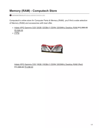
Memory RAM
Memory RAM. Mano and Kime Sections 6-2, 6-3, 6-4. RAM - Random-Access Memory. n-bit words. K Address lines can reference 2 k memory locations. Byte - 8 bits Word - Usually in multiples of 8. 00 01 10 11. b 1 b 2 b 3 b 4 … b n. 8 16 32. 10110101 1011010101101011

Memory RAM
E N D
Presentation Transcript
MemoryRAM Mano and Kime Sections 6-2, 6-3, 6-4
RAM - Random-Access Memory n-bit words K Address lines can reference 2k memory locations Byte - 8 bitsWord - Usually in multiples of 8 00 01 10 11 b1b2b3b4 … bn 8 16 32 10110101 1011010101101011 10110110101101101010101111100101
We call this a 1024 x 16 memory - 1024 memory locations ( 0 - 1023 ) that will each hold 16-bit words.
32K x 8 Static RAM 1 28 Vcc A14 __ 2 27 A12 WE 3 26 A7 A13 4 25 A6 A8 5 24 A5 A9 6 23 A4 A11 __ 7 22 A3 OE 8 21 A2 A10 __ 9 20 CE A1 10 19 A0 D7 11 18 D0 D6 12 17 D1 D5 13 16 D2 D4 14 15 GND D3 51256S
Static RAM A Static RAM cell - 1 bit Data In Complement ofData In When Select is 0, S = 0 , R = 0 S-R Latch is in No Change State Outputs C and /C are both 0 Recall... When Select is 1, the Data in and its complement get latched into the memory cell
A PARTICULAR BIT IN A SELECTED WORD 0110 1001 0100 0011 1110 1011 0111 1000 4 x 8 RAM 4 memory locations, 8 - bits each Bits are written in parallel
A 16 x 1 RAM Chip 16 memory locations, 1 bit each 2k locations with k select lines 2k=16, k = 4
1 1 1 1 0 Decoder controls Address Selecting 0 0 0 Address decoder enables the RAM cell for the 1-bit word selected and disables all others 1 Tri - State Buffer
Tri - State Buffer High Impedance Tri-state buffers can be connected together to form a multiplexed output line
Using a tri-state buffer for a multiplexed output The inverter ensures that the enable ‘select’ bits are always complements of eachother Both buffers are enabled at the same time thus both are ‘driving’ the same line at the same time OK if values are the same (both high or both low) but if ‘opposing’ values are presented then you can expect high current resulting in SMOKE!
Using a 4 x 4 RAM CELL to implement a 16 x 1 RAM
Row Select Column Select
An 8 x 2 RAM using a 4 x 4 RAM CELL Array Chip Select
1 18 D Vss 2 17 W Q 3 16 RAS CAS 4 15 TF A9 5 14 A0 A8 6 13 A1 A7 7 12 A2 A6 8 11 A3 A5 9 10 Vcc A4 1 Mbit (1,048,576) x 1 Dynamic RAM Need 20 address lines. Only have 10 address lines, A0 - A9. Multiplex lower and upper 10 address lines using RAS and CAS signals.
DRAM Bit Slice Model
Remember making a 4-to-16 decoder using 5 2-to-4 decoders… I3 I2 I1 I0 3 2 1 0 En En En En O15 O0
A 256K x 8 RAM using 4 64K x 8 RAM Chips The 2 most significant bits select the RAM chip The other 16 bits address the memory locations
How about a 64K x 16 RAM using two 64K x 8 RAM chips Most significant 8 bits Least significant 8 bits