Thermal Conductivity Characterization for Cryogenic Applications
190 likes | 432 Vues
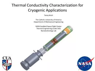
Tareq Alosh The Catholic University of America Department of Mechanical Engineering NASA Goddard Space Flight Center Thermal Engineering (Code 545) Nanotechnology Lab. Thermal Conductivity Characterization for Cryogenic Applications. Energy balance. Energy balance. where:.

Thermal Conductivity Characterization for Cryogenic Applications
E N D
Presentation Transcript
Tareq Alosh The Catholic University of America Department of Mechanical Engineering NASA Goddard Space Flight Center Thermal Engineering (Code 545) Nanotechnology Lab Thermal Conductivity Characterization for Cryogenic Applications
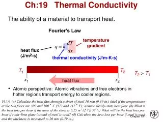
Energy balance where: • assuming uniform radial temperature and Note: Testing is performed under high vacuum, no convective heat transfer
Thermal network Isothermal
Original facility • Heat losses of up to 50% • Issues with instrumentation in measuring conduction • Inadequate design of radiation shielding • Lateral shifting of meter bars during testing • May be due to improper instrumentation as well as improper use of bellows pressurization system
PRTs are located closer to surface of meter bar and the assumption of radially uniform temperature is invalid given lateral shifting Actual heat transfer (in the normal direction) is located within the intersected areaand PRTs do not provide valid data. This may be one reason contractor was unable to fully account for heat flows
Proposed modifications The bellows pressurization system currently uses redirected air from the evacuation of the testing chamber. The air is cooled to the cryogenic regime, and condenses. This causes a decrease in pressure and thereby contact between sample and meter bars. It may also damage the bellows system. An independent helium system will be used and pressure on the meter bar system will be set by a pressure regulator. This will eliminate the load cell currently used to determine contact pressure, which is only accurate to a minimum temperature of - 50°C.
Proposed modifications Meter bars have been redesigned to use pure copper with an array of PRTs that will provide an accurate temperature distribution throughout cross-sectional area. Two holes have been designed perpendicular to the centerline of the cross- section to accommodate heater cartridges. Taps have been designed to hold heater cartridges flush and maintain internal contact to copper meter bar.
Heat flow metering assembly Fitting to independently regulated helium dewar Hot end meter bar Test specimen location Cold end meter bar Bellows system (2X) Copper meter bars
Thermal radiation considerations • Unwanted heat transfer may be due (partially) to radiation effects • Radiation shielding should be constructed of low conductivity materials to create isothermal conditions at any position along shield • Also beneficial in case of incidental contact • Proposed radiation shielding • Outer shell: Ultem [PEI] Tubing • Inner shell: Fiberfrax Insulation Blanket
Anticipated effects (using FEA) • With small temperature differences, the radiation shielding achieves a constant temperature • Radiation heat transfer becomes negligible in terms of heating load on cryocooler • PID control of hot end meter bar will maintain proper temperatures • Cryocooler is able to maintain a cold end temperature of 70 K
Small temperature differences(realistic testing conditions: ΔT ≈ 40 K)
Large temperature differences(operational limits: ΔT ≈ 450 K)
Preliminary radiation analysis • To achieve maximum temperature difference in meter bars (ΔT ≈ 450 K), 566 W is needed from cartridge heaters • This is a theoretical amount of heat used as a worst case scenario for radiation analysis • Parasitic heat transfer due to radiation is a roughly 8 W gain
Acknowledgements • Jeff Didion • NASA GSFC: Senior Thermal Engineer/Mentor • Mario Martins • Edge Space Systems: Thermal Laboratory Manager • Mark Kobel • NASA GSFC: Senior Thermal Engineer • Frank Robinson • NASA GSFC: Thermal Engineering Co-op • Elizabeth Hadley and David Jovel • NASA GSFC: Thermal Engineering Interns • Everyone in Code 545