Thermal Conductivity Detector
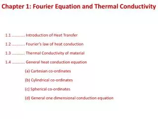
The Thermal Conductivity Detector (TCD) is the most universal detector available. Depending on the compound, the TCD responds with a detection range of 0.01% to 100% (100-1,000,000ppm). The SRI TCD consists of four filaments housed in a stainless steel detector block. Visit - http://quadrexcorp.com/<br>

Thermal Conductivity Detector
E N D
Presentation Transcript
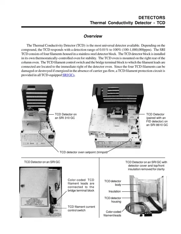
DETECTORS Thermal Conductivity Detector - TCD Overview The Thermal Conductivity Detector (TCD) is the most universal detector available. Depending on the compound, the TCD responds with a detection range of 0.01% to 100% (100-1,000,000ppm). The SRI TCD consists of four filaments housed in a stainless steel detector block. The TCD detector block is installed in its own thermostatically-controlled oven for stability. The TCD oven is mounted on the right rear of the column oven. The TCD filament control switch and the bridge terminal block to which the filament leads are connected are located to the immediate right of the detector oven. Since the four TCD filaments can be damaged or destroyed if energized in the absence of carrier gas flow, a TCD filament protection circuit is provided in all TCD-equipped SRI GCs. TCD Detector on an SRI 310 GC TCD Detector (paired with an FID detector) on an SRI 8610 GC TCD detector oven setpoint (trimpot) TCD Detector on an SRI GC TCD Detector on an SRI GC with detector cover and top/front insulation removed for clarity Color-coded TCD filament leads are connected to the bridge terminal block TCD detector body Insulation TCD detector housing TCD filament current control switch Color-coded filament leads
DETECTORS Thermal Conductivity Detector - TCD Theory of Operation The TCD detector measures the difference in thermal conductivity in the carrier gas flow and the analyte peaks. Every compound possesses some degree of thermal conductivity, and may therefore be measured with a TCD detector. Due to its high thermal conductivity and safety, helium carrier is most often used with TCD detectors. However, other gases may be used such as nitrogen, argon, or hydrogen. One of four TCD filaments TCD filament bridge R S S R The Wheatstone Bridge circuit design in the SRI TCD uses four general-purpose tungsten-rhenium filaments for sample analysis. Two of the filaments are exposed to the sample-laden carrier gas flow and provide the actual chromatographic signal. The other two filaments are provided with clean carrier flow, enabling them to be used as a baseline reference signal. When the effluent from the column flows over the two sample stream filaments, the bridge current is unbalanced with respect to the reference signal. This deflection is translated into an analog signal which is sent to the data system for analysis. The four pairs of filament leads are color-coded in two-color units; each color is used on two different leads. All eight wires are connected to the bridge current supply via four setscrew-type terminal connectors on the top control panel of the GC. Silkscreened labelling on the chassis indicates which color wire connects to each terminal. The TCD detector block is divided into two cells containing two filaments each. One cell holds the reference pair while the other cell holds the sample pair. All four TCD filaments are physically identical except for their color-coding. The carrier gas is plumbed so that is exits the Electronic Pressure Controller module, flows through the polishing filter, through the reference side of the TCD bridge, then through the injection port to the column, and from the column to the sample side of the TCD bridge. After the flow passes through the sample cell, it is directed back out of the TCD oven and into the column oven through the TCD detector outlet, where it may be routed to a subsequent detector or to vent. All four TCD detector inlet/outlet tubes are 1/16” stainless steel. Simplification of filament interconnection Red Color-coded filament leads Reference gas in Sample gas in Red Blue Green REFERENCE SAMPLE Blue Green Black Black SAMPLE REFERENCE TCD carrier gas flow diagram
DETECTORS Thermal Conductivity Detector - TCD Expected Performance TCD Noise Run Carrier: Helium @ 10mL/min TCD gain = LOW TCD temp = 100oC Temperature program: Initial Hold 80oC 15.00 Ramp Final 0.00 80oC TCD noise averages 10µV frompeak to peak Factory Test Run of a TCD-equipped SRI GC Sample: natural gas standard, 1mL sample loop Columns: 1m Molecular Sieve, 2m Silica Gel Events: Time 0.00 0.050 6.00 Event ZERO G ON (valve inject) G OFF Temperature program: Initial Hold 40oC 5.00 220oC 16.00 Ramp 10.00 0.00 Final 220oC 220oC Results: Component Retention Area Oxygen 1.633 N2 2.150 Methane 3.033 Ethane 7.550 CO2 9.983 Propane 13.683 Iso-Butane 18.150 N-Butane 18.766 Iso-Pentane 22.550 19.7500 121.0880 563.6130 128.2185 11.9860 113.9220 69.4960 67.4460 20.1490 N-Pentane 22.866 Total: 19.1560 1134.8245
DETECTORS Thermal Conductivity Detector - TCD Expected Performance TCD Room Air Analysis Column: 3’ Silica Gel Carrier: Helium at 10mL/min Sample: 0.5cc room air, direct injection TCD current: LOW TCD temperature: 100oC Temperature Program: Initial Hold 80oC 4.00 Ramp Final 0.00 80oC Results: Component O2 N2 CO2 Retention 0.716 2.766 Total Area 1021.3830 1.5060 1022.8890 The CO2 content of the room air analyzed is approximately 350ppm. TCD Breath Analysis Column: 3’ Silica Gel Carrier: Helium at 10mL/min Sample: 0.5cc human breath, direct injection TCD current: LOW TCD temperature: 100oC Results: Component O N CO2 Retention 0.700 2.700 Total Area 1379.4740 61.9540 1441.4280 2 2 Temperature Program: Initial Hold 80oC 24.00 Ramp Final 0.00 80oC
DETECTORS Thermal Conductivity Detector - TCD General Operating Procedure 1.Check to make sure that the TCD filament current is switched OFF. Plug in and turn on your GC. Allow the TCD detector oven to reach temperature (100oC) and stabilize. With the “DisplaySelect” switch in the UP position, press on the TCD Temperature Actual button on the front control panel to read the TCD cell temperature. The TCD oven block is set to 100oC at the factory, but is adjustable by turning the trimpot with a small blade screwdriver while observing the TCD BLOCK setpoint temperature on the digital display. The trimpot is located on the top edge of the GC’s front control panel, under the red lid. 2.All TCD-equipped SRI GCs are tested with a 1m, 1/8” stainless steel silica gel-packed column. The carrier gas head pressure is preset at the factory to 10mL/min for this type and size column. Look on the right side of the GC for the carrier pressure that correlates to a flow of 10mL/min. Because different columns require different flow rates, the carrier head pressure may be adjusted by the user with the trimpot above the “CARRIER1” buttons. 3.Make sure that the setpoint and actual pressures are within 1psi. 4.Damage or destruction of the TCD filaments will occur if current is applied in the absence of flowing carrier gas. ALWAYS verify that carrier gas can be detected exiting the TCD carrier gas outlet BEFORE energizing the TCD filaments. The carrier gas outlet tube is located on the outside of the Column Oven on the same side as the detector. Place the end of the tube in liquid and observe (a little spit on a finger can suffice). If there are no bubbles exiting the tube, there is a flow problem. DO NOT turn on the TCD current if carrier gas flow is not detectable. A filament protection circuit prevents filament damage if carrier gas pressure is not detected at the GC, but it cannot prevent filament damage under all circumstances. Any lack of carrier gas flow should be corrected before proceeding. 5.With the TCD filaments switched OFF, zero the data system signal. Switch the filaments to LOW. The signal’s deflection should not be more than 5-10mV from zero for a brand-new TCD detector. Any more than a 5-10mV deflection indicates partial or complete oxidation of the TCD filaments; more deflection means more oxidation. Therefore, it is a good habit to use the data system signal to check the working order of the TCD filaments. 6.In PeakSimple, set an isothermal column oven temperature ramp program as follows: Initial Temp. Hold Ramp Final Temp. 80oC 7.00 0.00 80oC 7.Zero the data system signal (clicking on the Auto Zero button at the left edge of the chromatogram window is one way to do it), then start the run (hit the computer keyboard spacebar or hit the “RUN” button on the GC). Auto Zero button 8.Inject sample. Injection volumes of 0.5mL for gas and 1µL for liquid is recommended to prolong TCD filament life.
DETECTORS Thermal Conductivity Detector - TCD TCD Filament Protection Circuit All TCD detectors are susceptible to filament damage or destruction if operated at high current in the absence of carrier and/or reference gas flow. The filaments will incandesce and burn out if the carrier or reference gas flow is interrupted due to a variety of possible factors such as a column break, inadvertent column disconnection during column changes, removal of the septum nut for septum replacement, or when the carrier gas cylinder runs dry during an analysis. The SRI TCD filament protection circuit is a current “cut-out” circuit that monitors the column head pressure during GC operation. Under normal circumstances, there is no reason for the column head pressure to drop below 3psi, with most columns operating at 8psi or above. When the head pressure sensor located in the carrier gas flow path drops below 3psi, the protection circuit is activated, and the current to the TCD filaments is interrupted immediately. A red LED on the GC’s front control panel under “DETECTORPARAMETERS” will light to indicate that the protection circuit has detected a gas pressure loss and shut down the filament current. The cause of the protection circuit activation should be immediately investigated and corrected. As an additional caution, use HIGH current only with helium or hydrogen carrier gases. With nitrogen carrier, use LOW current only, or the filaments may be damaged. The pressure at which the protection circuit activates is user adjustable with the trimpot on the top edge of the front control panel, above the label reading “TCDPROTECT.” Bright red LED display TCD protection circuit LED lit on an SRI model 8610 GC front control panel 1- 2- 3- 4- 1- LOCAL SETPOINT button 2- TOTAL SETPOINT button 3- STATUS LED 4- ACTUAL button LED panel displays control data corresponding to the button pressed The DISPLAY SELECT switch allows the user to choose between displaying the control zones using the buttons or the column oven temperature 1-Pressing the LOCAL SETPOINT button displays the filament cut-off setpoint value (factory set at 3psi) in the bright red LED display in the upper right corner of the GC’s front control panel. If the carrier gas pressure reaches or falls below this value, the filament current will immediately be interrupted. 2-Pressing the TOTAL SETPOINT button displays the carrier gas pressure present in the GC system. Under normal operation, this value will be well above the 3psi cut-off setpoint. 3-The STATUS LED glows bright red only when the TCD protection circuit has been activated. 4-Pressing the ACTUAL button displays the voltage present across one half of the TCD bridge. A value of 3.5 to 4.5 volts is typical when using high current; low current will display 2.5-3.5 volts (note: the LED displays 4 volts as “400,” 3.5 as “350,” etc.). Any value lower than these indicates a potential problem in the TCD detector bridge.