Synchronous Machine
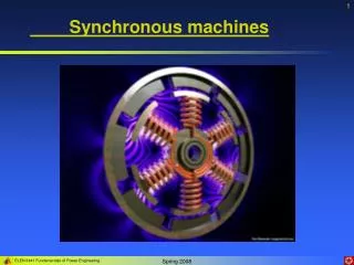
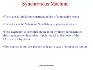
Synchronous Machine. Unit -V. Construction. Stationary armature , rotating field type of construction is preferred. High speed alternators have non-salient pole rotor (Turbo alternators) and they have either 2-pole or 4-pole.(Dia:1.2m; V a about 175m/sec)

Synchronous Machine
E N D
Presentation Transcript
Synchronous Machine Unit -V
Construction • Stationaryarmature, rotating field type of construction is preferred. • High speed alternators have non-salient pole rotor (Turbo alternators) and they have either 2-pole or 4-pole.(Dia:1.2m; Va about 175m/sec) • Slow speed alternators have salient pole rotor (water wheel alternators) and they have more than 4 poles.(Speed : 50 to 500RPM; Va is limited to 80m/sec) • Motors provided with damper windings • Compensators with rating upto 100MVAr and speed upto 3000RPM.
Runaway Speed: • It is the speed which the prime mover would have, if it is suddenly unloaded, when working at its rated load. • Runaway speeds of various water wheel turbines: • Salient pole machines: Designed to withstand mechanical stresses encountered at runaway speeds
Output Equation Q = Co . D2 L ns where, C0 – 11 Bav .ac.Kws X 10-3
Choice of Specific Magnetic Loading(Bav): • Iron loss: High Bav → high flux density in the teeth and core → high iron loss → higher temperature rise. • Transient Short Circuit Current: High Bav → low Tph → low leakage reactance (Xl)→ high short circuit current • Voltage Rating: In high voltage machines slot width required is more to accommodate thicker insulation →smaller tooth width → small allowable Bav • Stability : Pmax =VE/Xs . Since high Bav gives low Tph and hence low Xl increases Pmax and improves stability. • Parallel operation : Ps = (VE sinδ)/Xs ; where δ is the torque angle. So low Xs gives higher value for the synchronizing power leading stable parallel operation of synchronous generators. • Guide lines : • Non-salient pole alternator : 0.54 – 0.65 Wb/m2 • Salient – pole alternator : 0.52 – 0.65 Wb/m2
Choice of Specific Electric Loading: • Copper loss and temperature rise: High value of ac → higher copper loss leading high temperature rise. So choice of depends on the cooling method used. • Operating voltage : High voltage machines require large insulation and so the slot space available for conductors is reduced. So a lower value for ac has to be chosen. • Synchronous reactance (Xs) : High value of ac results in high value of Xs , and this leads to a) poor voltage regulation b) low steady state stability limit. • Stray load losses increase with increase in ac. • Guide lines : • Non-salient pole alternators : 50, 000 – 75,000 A/m • Salient pole alternators : 20,000 – 40,000 A/m
Round Pole Rectangular Pole Design of Salient Pole Machines: • Main Dimensions: • D & L • D:Depends on type of pole & Va • Two types of salient poles: • Round pole • Rectangular Pole • Round Poles: • Ratio: b/τ=0.6 to 0.7 (Sq.Pole Shoes) • Length of pole,L=Width bs • Length of pole,L=Length of Stator Core • Rectangular Poles: • Ratio: b/τ=1 to 5 • Maintained as 3 for economic field system • Peripheral Speed: • Depends on type of pole attachment • Bolted pole structure: 50m/s • Dovetail construction: 80 m/s
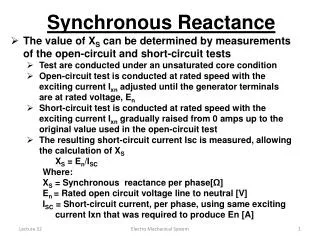
OCC SCC A 1.0 B p.u current p.u voltage C Fs 0 F0 1.0 p.u field current Short Circuit Ratio(SCR): • OFO- p.u field current required to develop rated voltage on OCC • OFs- p.u field current required to develop rated current on SCC • From the graph, • OFO=CFO & OFS=BFS=AFO
Short Circuit Ratio(SCR): • Thus SCR is the reciprocal of Xd • For Non-salient pole alternators : 1- 1.5 • For Salient pole alternators : 0.5 – 0.7 • Effect of SCR on machine performance • Voltage regulation : A low SCR → high Xd → large voltage drop → poor voltage regulation.. • Parallel operation : A low SCR → high Xd → low synchronizing power → parallel operation becomes difficult. • Short circuit current : A low SCR → high Xd →low short circuit current. But short circuit current can be limited by other means not necessarily by keeping a low value of SCR. • Self excitation : Alternators feeding long transmission lines should not be designed with small SCR as this would lead to large terminal voltage on open circuit due to large capacitance currents. • High value of SCR i) High stability limit, ii) Low voltage regulation, iii) High short circuit current and iv)Large air gap-large field-costlier. • Modern design is with low SCR.
Length of Airgap • The length of air gap very much influences the performance of a synchronous machine. • A large airgap offers a large reluctance to the path of the flux produced by the armature MMF and thus reduces the effect of armature reaction. • Thus a machine with large airgap has a small Xd and so has, • Small regulation • High stability limit • High synchronizing power which makes the machine less sensitive to load variations • Better cooling at the gap surface • Low magnetic noise and smaller unbalanced magnetic pull • But as the airgap length increases, a large value of Field MMF is required resulting in increased cost of the machine. • In salient pole machines, the airgap is not uniform throughout the pole arc. • Attempt is made to obtain sinusoidal distribution of flux by proper shaping and proportioning of pole shoe. • For salient pole machines with open slots, • For the machines designed for max. output equal to 1.5 times of rated output,
Length of Airgap Estimation of air gap length: No-load field MMF per pole =Armature MMF per pole X SCR ATfo =ATa.SCR Thus the value of no load MMF per pole can be estimated by assuming a suitable value of SCR MMF required for air gap= 0.8ATfo
Armature design • Windings used may be of single layer or double layer type • Machines with large value of flux per pole have small number of turns per phase and therefore double layer bar windings are used • High voltage machines and machines with small value of flux per pole have large number of turns per phase and therefore multi turn coils are used • In modern practice, it is employ double layer wave or lap winding COIL SPAN: • Coil span for the winding are chosen such that harmonics are reduced. • Highest amplitude harmonics in the flux distribution curve of salient pole generators are likely to be 5th or 7th • Max reduction of this harmonics is given by coil span of 8.33 % of pole pitch
Armature design Number of armature slots: • Balanced windings: number of arm slots must be such a number that a balanced windings is obtained • Cost : A smaller number of slots leads to a slight saving because there are fewer coils to wind, form insulate , place into slots and connect • Hot Spot Temperature: A smaller number of slots results in bunching of conductors, leaving smaller space for the circulation of air, gives rise to high internal temperatures • Leakage reactance: when the number of slots is small, leakage flux and therefore, leakage reactance is increased owing to conductors lying near each other • Tooth ripples: tooth ripples in field form and pulsation losses in the pole face decrease if a large number of slots are used • Flux density in iron: With larger number of slots , a greater space is taken up by the insulation, results in narrower teeth giving B beyond the limits
Armature design • Value of slot pitch(ys) guides for choosing number of armature slots • ys – depends on the voltage of the machine • ys ≤ 25 mm for low voltage machines • ys ≤ 40 mm for 6 KV & low voltage machines • ys ≤ 60 mm for machines upto 15KV • In salient pole machines, number of slots per pole per phase is usually between 2 to 4 • Fractional slot windings are invariably used in synchronous generators
Armature design Turns per Phase: • Flux per pole Ф = Bavτ L • Therefore, Turns/phase, Tph = Eph/(4.44 Ф f Kw) • The above relation is applicable when all turns of a phase are connected in series. But if there are ‘a’ parallel paths per phase,
Armature design Armature Conductors: Current in each condcutor, If there are ‘a’ parallel paths, then Iz= Iph/a For normally cooled machines , permissible δa - 3 to 5 A/mm2 as =Iz/ δa Slot dimensions: Bt – 1.7 to 1.8 T; Parallel sided slots are used Max. permissible width of slot Ws(max) = ys- Wt(min) Depth of the slot = 3 Ws
Armature design Length of the mean turn: • Lmt = 2L + 2.5τ + 0.06 KV + 0.2 Stator bore: • Depth of core, dc – can be calculated by assuming a suitable value of Bc • Bc – 1.0 to 1.2T • dc = Ф/(2 Li Bc) • Outer diatmeter = Do = D + 2(ds + dc)
Design of Turbo Alternators Output equation:
Design of Turbo Alternators Length of the air gap: Approx. value of ac per pole = ac.τ Armature MMF per pole, ATa= ac.τ/2 Therefore, No-load field MMF, ATfo = SCR X ATa ATfo = SCR X (ac.τ/2) SCR ranges between 0.5 & 0.7 Assuming 80% of no-load MMF to be lost in the air gap MMF required for air gap = 0.8 . ATfo = 0.8. SCR. ac.τ/2 But MMF required for air gap = 80000 Bg.lg.Kg From the above two expressions, Taking sinusoidal distribution of flux , In general Bg= 1.5 Bav and Kg = 1.1
Design of Turbo Alternators Stator Design: • No of stator slots per pole per phase – 2 to 4, but in case of turbo alternators it is – 8 or 9 • Slot pitch – 25 to 60, but in case of large turbo alternators it may be even – 75 to 90mm • Single layer concentric winding or double layer short pitched winding may be used • Current density – 8 to 9.5 A/mm2
Procedure for rotor winding design 1. Full load field mmfATfl = 2 ATa where ATa =2.7 . Iph. Tph. Kw/P 2. A standard exciter voltage may be taken. About 15 to 20% of this voltage is kept in reserve. Let Ve –be the exciter votlage Voltage across the field coil, Ef= (0.8 to 0.85)Ve/P 3. Lmtf = 2L + 2.3τ + 0.24 4. Voltage across field coil Ef= If.Rf 5. Assume suitable value of δf for field winding Total area of field conductors, Number of field conductors Conductors per slot
Computer Aided Design: Advantages of CAD: • Capability to store amount of data, count registers, round off results down to integers, refers to tables, graphs …. • Possible to select an optimized design with a reduction in cost and improvement in performance • High speed , less duration • Automatic operation • Easier to compare different designs, out of which the best suited can be selected • Reduced error, more accurate and reliable • Less cost • Capable of taking logical decision itself, thereby saving the man hour of the design engineers
Computer Aided Design: Different Methods: • Analysis method • Synthesis method • Hybrid method
Computer Aided Design-Analysis Method: Start Human Decisions Is Decision ok? Input Stop Performance Calculations Output
Computer Aided Design-Analysis Method: • In this method , the choice of dimensions , materials and types of construction are made by the designer and these are presented to the computer as input data. • Performance is calculated by the computer and is returned to the designer to examine • Designer examines the performance and makes another choice of input, if necessary and the performance is recalculated. • Procedure is repeated over and over again till the performance requirements are satisfied. • This method is an excellent for the beginners in computer aided design • Use computer only for the purposes of analysis leaving all exercises of judgment to the designer
start Computer Aided Design-Synthesis Method: Performance specifications Assume suitable values for variables Design calculations Performance calculations Adjust values for variables Compare calculated and desired performance Is Performance satisfactory? No Stop Calculate total cost Print design values Yes
Computer Aided Design-Synthesis Method: • Desired performance is given as input to the computer • Logical decisions are taken by the computer ( given as set of instructions) • Satisfies a set of specifications or performance indices • Saves time • But takes too much of logic since the logical decisions are taken by PC • Too complex & high cost