Towards a 7-module Micromegas Large TPC prototype
150 likes | 171 Vues
This project focuses on developing a 7-module Micromegas Large TPC prototype, with a goal of integrating more electronics, implementing new data acquisition methods, and achieving ILC compatibility. The backend hardware includes advanced components like FPGAs, optical links, and memory interfaces. The prototype is being tested and will undergo further improvements for multi-module operation and power pulsing tests. Future plans involve collaboration for a new 64-channel chip for enhanced performance and flexibility in particle detection applications.

Towards a 7-module Micromegas Large TPC prototype
E N D
Presentation Transcript
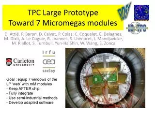
RD51 Towards a 7-module Micromegas Large TPC prototype D. Attié, P. Baron, D. Calvet, P. Colas, C. Coquelet, E. Delagnes, M. Dixit, A. Le Coguie, R. Joannes, S. Lhénoret, I. Mandjavidze, M. Riallot, S.Turnbull, Yun-Ha Shin, W. Wang, E. Zonca LCWS Geneva 1
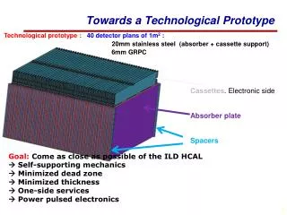
Large Micromegas TPC Prototype First phase with 1 module in the centre, T2K electronics : finished. 5 modules (of which 4 resistive) tested and worked well. Detailed analysis in progress 7 Micromegas modules - LCWS Geneva
Phase 2: Fully integrated 7 modules • Goal: Fully equip 7 modules with more integrated electronics, still based on the T2K AFTER chip. • Fit the electronics in 3 cm behind the modules • Make a backend able to read up to 12 modules • Go to fully ILC-compatible DAQ • New zero-suppression scheme • Air cooling • Multi-module software: alignment • quasi-industrial production and quality check of 9 modules (in clean room at CERN used by T2K) 7 Micromegas modules - LCWS Geneva
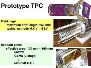
Back End • Functionalties • Receives clock, trigger and data flow controle and distributes them to FEMs (up to 12) by optical fibres • Concentrates data from 12 FEMs and send them to DAQ • Interfaces • 12 2-Gbit/s optical links • DAQ – Slow Control 1-Gbit/s link • fast Trigger – Clock link 7 Micromegas modules - LCWS Geneva
Back End Hardware • ML523 development kit from Xilinx • vc5vfx100t FPGA from Virtex-5 device family • Embedded PowerPC • 16 Multi Gigabit Transceivers • Embedded Ethernet MAC • 128 Mbyte DDR2 memory • RS232 interface • Up to 3 4-channel SMA-SFP interface cards • 2 Gbit/s optical transceivers for FE links • RJ45 Ethernet transceiver for the DAQ link • Trigger – Clock – Fast Control link mezzanine card 7 Micromegas modules - LCWS Geneva
Back End status: ready and tested With up to 12 FEM cards (old and new) Fully tested up to DAQ with 1 old FEM and 6 old FECs 7 Micromegas modules - LCWS Geneva
Front End Mezzanine (module card) 30 pins connector 30 pins connector 30 pins connector 30 pins connector 30 pins connector 30 pins connector One per module, 1728 channels.Gathers the signals from 6 FECs and sends them to the Back End with optical links SRAM ADC Xilinx Prom FPGA Xilinx V5 Optical connector Test Pulser 30 pins connector 30 pins connector 30 pins connector 30 pins connector 30 pins connector 30 pins connector 24 rows x 72 columns <pad size> ~ 3x7 mm2 7 Micromegas modules - LCWS Geneva
Front End Mezzanine Status : 2 prototype cards ready and tested: fully operationnal 7 Micromegas modules - LCWS Geneva
Status : 8 cards ordered, being built Ready for testing mid-November ? Front-End Cards Naked chip on board High density connectors Power dissipation opposite to gas volume 7 Micromegas modules - LCWS Geneva
New detector module Based on experience from single-module tests: Same pattern, but routing adapted to new flat connectors. New via filling technique. Use CLK with 2-3 Mohm/square resistivity New grounding of the resistive foil on the sides of the modules, by metallization: no dead space. Back from the PCB maker these days. Will be equipped with a resistive bulk in the next few weeks at CERN workshop. 24 rows x 72 columns <pad size> ~ 3x7 mm2 7 Micromegas modules - LCWS Geneva
Summary: 7 modules & New T2K Electronics FLAT ON THE BACK OF THE MODULE Test 1 module with full chain early 2011. Build in a quasi-industrial process 9 modules in 2011, and characterize them. Perform multi-module tests in 2012 and following years. Use the same cards for a power-pulsing test in the DESY 5T magnet. 7 Micromegas modules - LCWS Geneva
Multi-module Software Display program GEAR-integrated geometry with free translations and rotation angles w.r.t. central module Track reconstruction and fitting by Kahlman filter, integrated in Marlin TPC Simulation integrated in Marlin TPC Analysis (study of resolution and distortions, correction for non-uniformity) integrated in Marlin TPC 7 Micromegas modules - LCWS Geneva
Power pulsing test with Saha and Carleton in the 5T magnet Goal : check that 55Fe parameters are stable with power pulsing (both on mesh readout and pad readout) and study mechanical effects in high B field. 7 Micromegas modules - LCWS Geneva
Future : S-ALTRO64 Collaboration within AIDA (CERN Lund Saclay) towards a 64-channel chip with integrated ADC. Will probably be thought as modular (multi-chip modules bonded on small cards The final electronics (SALTRO 64?) willbe usable for both GEM and Micromegas. The AFTER-basedelectronics, using a SCA, is not extrapolable to a depthmatching the ILC train length. 7 Micromegas modules - LCWS Geneva