Download
1 / 19
190 likes | 359 Vues
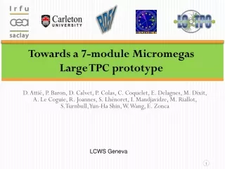
Single-module tests of a Micromegas TPC for the LC. P. Colas on behalf of LCTPC. Strategy for Micromegas. The Micromegas option is studied within the same (EUDET) facility as the other options ( see R. Diener’s talk), and also in hadrons beams at CERN (RD51)

E N D
Single-module tests of a Micromegas TPC for the LC P. Colas on behalf of LCTPC
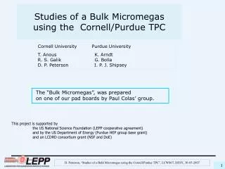
Strategy for Micromegas • The Micromegas option isstudiedwithin the same (EUDET) facility as the other options (see R. Diener’s talk), and also in hadrons beamsat CERN (RD51) • Phase I: ‘Large Prototype’ Micromegas modules werebuilt and tested in beam (2008-2011): 7 up to nowwithvariousresistivecoatings, PCB routings and technology, electronicintegration, etc… • Phase II(2011-2012): build 9 identical modules and address all integration issues, serial production and characterization, multimodule issues (alignment, distortions). • This talk: resultsfrom Phase I and status of Phase II. P. Colas - Micromegas TPC tests
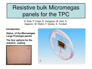
Charge spreading by resistive foil Resistivecoating on top of an insulator: Continuous RC network whichspreads the charge: improves position sensitivity M. Dixit, A. Rankin, NIM A 566 (2006) 28 Variousresistivecoatings have been tried: Carbon-loadedKapton (CLK), 3 and 5 Mohm/square, resistiveink. P. Colas - Micromegas TPC tests
Relative fraction of ‘charge’ seen by the pad, vs x(pad)-x(track) Pad response Z=20cm, 200 ns shaping 24 rows x 72 columns of 3 x 6.8 mm² pads x(pad) – x(track) (mm) P. Colas - Micromegas TPC tests
Uniformity (B=1T data) MEAN RESIDUAL vs ROW number Z-independentdistortions Distortions up to 50 microns for resistiveink (blue points) Rms 7 microns for CLK film (red points) -> select CLK Z=5cm Z=35cm Z=50cm Rownumber P. Colas - Micromegas TPC tests
Uniformity z distribution Average charge by row • Average charge by row Using cosmic-ray events B=OT Using 5 GeV e- B=1T 0 5 10 15 20 0 5 10 15 20 Excellent uniformity up to the edge of the module, thanks to the ‘bulk’ technology. P. Colas - Micromegas TPC tests
Data analysis results (B = 0T & 1T) Carbon-loaded kapton resistive foil Gas: Ar/CF4/Iso 95/3/2 Cd : diffusion constant B=0 T Cd = 315.1µm/√cm (Magboltz) B=1 T Cd = 94.2µm/√cm (Magboltz) Module 3 χ2: 29.1 Ndf: 11 Module 4 • χ2: 10.6 Ndf: 10 P. Colas - Micromegas TPC tests
Neff measurementwithMicromegas Averaging B=0T and B=1T data, modules 4, 5 and 3 (excluding ink module): • Neff = 38.0±0.2(stat) (systematics difficult to assess) • σ0= 59 ± 3 µm Note that 1/<1/N> = 47.1 from Heed for 5 Gev electrons on 6.84mm long pads. Thus Neff has to be between 23.5 (for exponential gain fluctuations) and 47.1 if there are no gain fluctuations. 1/<1/N> = 34.9 for 5.4 mm pads (GEM case). D. Arogancia et al., NIM A 602 (2009) 403 P. Colas - Micromegas TPC tests
Dependence of resolutionwithpeaking time Z=5cm CLK 5 MW/sq Optimum resolution for 500 ns peaking time -> try to lowerresistivity to lowerthispeaking time (faster charge spreading) P. Colas - Micromegas TPC tests
Test in a high intensity p beam Top 40 cm B field 11 cm 27 cm 35cm Bottom P. Colas - Micromegas TPC tests
Test at CERN (July 2010) at 180 kHz (5 x 2 cm² beam) showed no charging up and stable operation • Peaking time of 200 ns isenough to obtain the best resolution -> 300 ns suffice to distinguish 2 tracks on the same pad 4µs Time (in 40 ns bins) P. Colas - Micromegas TPC tests
Towards Phase II: 7 module project – electronic integration P. Colas - Micromegas TPC tests
May 2011: beam test of a new module withfullyintegratedelectronics • New detector : new routing to adapt to new connectors, lower anode resistivity (3 MW/sq), new res. foil grounding on the edge of the PCB. • New 300 points flat connectors • New front end: keepnaked AFTER chips and remove double diodes (count on resistive foil to protectagainstsparks) • New Front End Mezzanine (FEMI) • New backendready for up to 12 modules • New DAQ, 7-module ready and more compact format • New trigger discriminator and logic (FPGA). P. Colas - Micromegas TPC tests
Integrated electronics for 7-module project 25 cm • Remove packaging and protection diodes • Wire –bond AFTER chips • Use 2 × 300 pins connector • Use tiniest resistors (1 mm × 0.5 mm) from O to 10W FEC 4,5 cm 12,5 cm 14 cm 3,5 cm 2,8 cm 0,78 cm 3,5 cm Chip 0,74 cm • after 2 weeks of operation: no ASIC lost: • The resistive foil protects against sparks P. Colas - Micromegas TPC tests
First prototype of the electronics P. Colas - Micromegas TPC tests
Thermal studies. IR camera shows hot spots (regulators, ADC). T-probes on every component. • 2-phase CO2 coolingunderstudy (KEK, Nikhef) Onset of the electronics Nitrogencooling P. Colas - Micromegas TPC tests
Preliminary results : resolution (B=1T data) • Tends to confirmpreviousmeasurements (excludinglineswithASICs in bad contact). • Optimum resolutionnowobtained for peaking time below 200 ns Resolution vs z for variouspeaking times. P. Colas - Micromegas TPC tests
CONCLUSIONS • A baseline Micromegas module for ILC TPC isnowwelldefined, withveryhigh performances : 60 µ resolution for 3mm-wide pads, Neff = 38. • A module withfullyintegratedelectronics has been tested in a beam and showedsimilar performance • A serial production and characterizationwillbecarried out in 2012. A test benchat CERN willbeused to study the uniformity and thermal properties. P. Colas - Micromegas TPC tests