TDC Review
Detailed report on TDC board issues, solutions, and future orders. Includes history, problems encountered, personnel involved, timing studies, options for readout speed, and operational experience.

TDC Review
E N D
Presentation Transcript
TDC Review Report to the TDC Review Committee Presented by Myron Campbell TDC Review
History • First version JMC96 – April 1994 • Second version JMC96 – May 1995 • Third version JMC96 – February 1996 • Fourth version JMC96 – June 1996 • Final version JMC96 – August 1996 • TDC 16A – 1994 • TDC 16B – 1995 • TDC 96A – 1996 • TDC 96B – 1997 • TDC 96C – 1998 • TDC 96D – March 1999 • TDC 96E – June 2002 TDC Review
Delivery of TDC’s • The first order of boards were difficult to get to work. There were problems with vias, most boards had one or more random signal which was not connected. We could deliver about 7 boards per week. • The last order order of 180 boards were much easier to make work. When not limited by delivery of boards we could produce 45 per week. TDC Review
List of Problems • Bad vias • Blown buffer chips • TDC Crate Hangs • Mezzanine timeout • Readout errors • An extra word is read out of the FIFO at the end of block transfer read. • Individual boards can hang requiring a VME reset. • Data corruption when reading the Done register while the DSP was processing hits • Data corruption when reading the FIFO while the DSP was processing hits • Noise on the Level one accept signal to the bunch counter caused the bunch counter error • Termination on DSP data lines caused occasional corruption • FIFO reset not being generated by DSP reset • Possible hang in timeout circuit when reading mezzanine registers when no mezzanine card is installed TDC Review
Placing next order • Will order 200 boards • Based on analysis by Cathy • 125 LVDS boards • 75 ECL boards • Establish parts acquisition • Most parts will be purchased by assembly house • We will supply some connectors, programmed logic, and TDC chips • Modify design • All ECO’s will be incorporated into new design. Cross talk analysis will be redone. A few corrections will be made to the new boards to improve signal quality. TDC Review
Schedule TDC Review
Schedule TDC Review
Placing Next Order • Manufacture 20 boards, assemble • Since we have a new design we will have to test with 20 boards. • Will change from OPC to white tin copper coating • Follow with full production • Expect full production can start in August. • Expect to be able to test and deliver 45 boards per week. TDC Review
Michigan teststand Calibration XFT tests Muon tests VME debugging Fermilab teststand COT teststand Muon teststand PREP teststand TDC Teststand TDC Review
Personnel • Jon Ameel • Electronics shop supervisor – trains and supervises students to do assembly and test • Claudio Ferretti • Post Doc – Maintain code on test stands. Create new DSP code • Monica Teccio • Post Doc – Create schematics and artwork for new boards • Kathy Copic • Graduate Student TDC Review
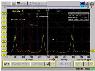
Timing studies • We are issuing a Level 2 accept for event N+1 before the data from event N is read from the FIFO. • The DSP takes time to read and format the TDC data. This takes place on all boards in the crate at the same time. The DAQ system reads from the FIFO one board at a time. • Have a plot of readout time. Have plotted the number of hits per channel, assumed uniform, and assume 18 TDC cards per crate. • The following is the prediction of the time needed to process the event. The prediction was made in January, 2001 TDC Review
DSP and Readout time TDC Review
Options to speed up readout • TDC’s were designed for 300 Hz • To make work at 1000 Hz have to: • Decrease time spent by DSP • Decrease time to readout • Decrease amount of data readout TDC Review
Decrease DSP time • Probably only a few percent available with current scheme • Reduce the data formatting done by the DSP – would require moving away from COTD format • Use 72 channels per card for the 9 highest occupancy cards • Reduce maximum number of hits per channel • See Ron Moore’s talk for more details TDC Review
Decrease time to readout • Implement SPY mode in tracer • Split the crate into two backplane segments • See Arnd’s talk for more details TDC Review
Decrease amount of data readout • Reduce the maximum number of hits per channel • Compress the data – 3 hits per 2 words • Discard data such as short pulses, early pulses, or late pulses. TDC Review
Operations Experience • The Time to Digital Conversion part of the TDC’s work very well. Can reconstruct tracks. • After the boards were installed and not moved they were reasonably reliable – no solid evidence of vias continuing to fail • Each improvement of the DAQ system uncovered additional problems in the design or layout of the TDC board • Need to continue to run crates full of boards at high speed. • Need careful monitoring and diagnosis of any problem that appears in these tests. TDC Review