Steel Tension Members Design: AISC Chapter D Summary
120 likes | 182 Vues
Learn about designing steel tension members, calculations, failure prevention, and AISC guidelines. Understand member connection, gusset plate, and effective net area considerations. Explore yielding and fracture limits, bolted & welded connections, and threaded rod design strength.

Steel Tension Members Design: AISC Chapter D Summary
E N D
Presentation Transcript
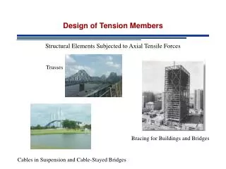
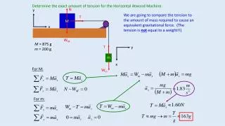
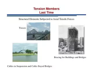
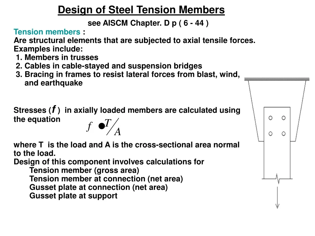
Design of Steel Tension Members see AISCM Chapter. D p ( 6 - 44 ) Tension members : Are structural elements that are subjected to axial tensile forces. Examples include: 1. Members in trusses 2. Cables in cable-stayed and suspension bridges 3. Bracing in frames to resist lateral forces from blast, wind, and earthquake • Stresses (f ) in axially loaded members are calculated using the equation where T is the load and A is the cross-sectional area normal to the load. • Design of this component involves calculations for • Tension member (gross area) • Tension member at connection (net area) • Gusset plate at connection (net area) • Gusset plate at support
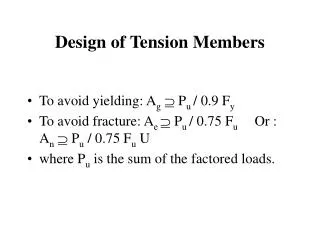
Max stress Fy Tu Tu Max stress Fu A tension member can fail by: 1. Excessive deformation (yielding) - Excessive deformation is prevented by limiting stresses on the gross section to less than the yield stress. For yielding on the gross section, the ultimate strength is: Tu = φtTn =φtFy Ag and φt=0.90 2. Fracture - Fracture is avoided by limiting stresses on the net section to less than the ultimate tensile strength. For fracture on the net section, the ultimate strength is: Tu = φtTn = φt FuAe and φt=0.75 And finally Tu = 0.9 Fy Ag or = 0.75 FuAe( smaller value will govern )
see AISCM Chapter. B p ( 6 - 34 ) The AISC Steel Manual determines the effective net area as follows: For bolted connections: Ae = UAn For welded connections: Ae = UAg An - Net cross-sectional area(gross-section minus bolt holes) Ag – Gross cross-sectional area Ae – Effective net area where and is the distance from the plane of the connection to the centroid of the connected member and L is the length of the connection in the direction of the load. If tension load is transmitted directly to each of the cross-sectional elements by fasteners or welds: Ae = An i.e U = 1.00
Variable Definitions • Resistance factor, = 0.90 for yielding = 0.75 for fracture • Fy = Yield Strength • Fu = Tensile or Ultimate strength
Example of tension transmitted by some but not all of cross-section L –shape with bolts in one leg only Reduction coefficient, Where is the connection eccentricity
Staggered Fasteners All possible failure patterns should be considered
Threaded Rod Tension on the effective net area Tn = AsFu = 0.75AbFu , where As is the stress area (threaded portion), Ab is the nominal (unthreaded area), and 0.75 is a lower bound (conservative) factor relating As and Ab. The design strength of a threaded rod is calculated as: Tu= Tn =0.75 Tn i.eTu = 0.75 AsFu or = 0.75 x 0.75AbFu = 0.5625 AbFu