SUBSURFACE EXPLORATION
SUBSURFACE EXPLORATION. M. Zoghi, Ph.D., P.E. Geotechnical Design Fall 2007. OUTLINE. Overview Literature Search – “Desk Study” Reconnaissance Survey Preliminary Investigation Detailed Investigation Geotechnical Report. I. Overview - Typical Project. Project Initiation

SUBSURFACE EXPLORATION
E N D
Presentation Transcript
SUBSURFACE EXPLORATION M. Zoghi, Ph.D., P.E. Geotechnical Design Fall 2007
OUTLINE Overview Literature Search – “Desk Study” Reconnaissance Survey Preliminary Investigation Detailed Investigation Geotechnical Report
I. Overview - Typical Project • Project Initiation • Review Existing Data • Meet with Structural Engineer • Perform Subsurface Exploration Program • Perform Laboratory Analysis and Testing • Perform Design Analysis • Prepare Geotechnical Investigation Report • Review Final Plans and Specifications • Establish Construction Criteria • Troubleshoot Construction Problems
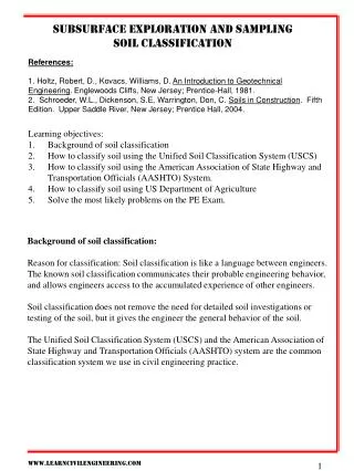
Objectives of Site Exploration • To identify the location & thickness of soil & rock stara • To verify the character and location of the GWT • To obtain soil/rock specimens for testing and evaluation • To determine the relevant engineering properties • To identify potential problems (expansive, collapsible…) • To establish construction procedures for altering subsoil conditions • To estimate settlement, bearing capacity, lateral earth pressure distribution, etc. • To determine the type and depth of suitable foundation system.
Uncertainties • Predict subsurface conditions between the borings based on local geology • Observe and inspect soil conditions during construction and modify design as deemed appropriate along with a post-construction monitoring plan • Accept and acknowledge some risk of failure due to unforeseen conditions • Use higher factors of safety in design and apply appropriate conservatism
Project Assessment • Obtain the preliminary project data such as the building/bridge plan, column location, etc. • Identify the type of construction, structural loads, etc. • Obtain the existing topography and proposed grading • Establish allowable settlements
II. Literature Search – “Desk Study” • Geologic maps – such as the USGS maps • Soil survey reports – USDA reports for each county • Soil’s reports – existing nearby projects • Aerial photographs • Historic groundwater data – US Corps of Engineers, etc. • Public libraries
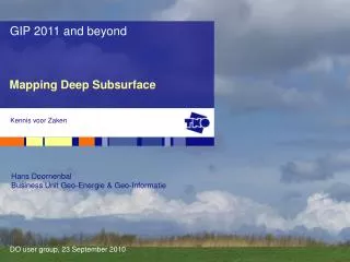
Idaho is an igneous state, built from many different episodes of volcanism and intrusion, plus vigorous uplift and erosion by ice and water. Its two largest features are the great Idaho batholith, a huge emplacement of plutonic rock of Mesozoic age, and the swath of lava beds across the south that marks the path of the Yellowstone hotspot. http://geology.about.com/library/bl/maps/blidahomap.htm
III. Reconnaissance – Visual Inspection of the Site • Inspect the general topography of the site and verify the presence of drainage ditches, vegetation, abandoned dumps and debris, or other material • Inspect the conditions of nearby structures … • Verify the types of exposed soil/rock at the ground surface • Inspect the soil stratification of nearby deep excavations • Inspect high-water marks on buildings and bridge abutments • Look for signs of distresses in pavements, other shrinkage crack patterns, and creep of slopes
IV. Preliminary Investigation Abandon Adapt Alter
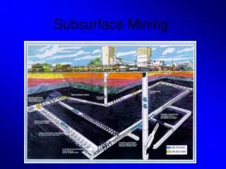
V. Detailed Investigation • Spacing and depth of borings • Sampling • Groundwater • Other details
Spacing Source: Das, 2002
Minimum Depth of Borings Subsurface Conditions Min. Depth of Borings Poor 6S0.7+ D (m) Average 5S0.7+ D Good 3S0.7 + D S = No. of Stories, D = Anticipated Depth of Foundation
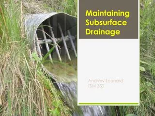
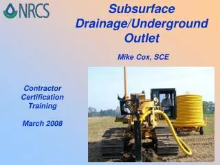
Hand Augering and Core Sampling for Collection of Shallow Soil Samples Auger to desired depth Extract auger and insert core sampler Drive core sampler Extract core sampler Remove split spoon from shaft If shelby tube, cap and store If split core, open and slide into sterilized collection jar Wash equipment (steam clean, as required) prior to collection of next sample http://www.cee.vt.edu/ewr/environmental/teach/smprimer/core/core.html
Continuous Flight Augers http://www.drilleronline.com/CDA/ArticleInformation/features/BNP__Features__Item/0,3643,138082,00.html
Drill Rig http://en.wikipedia.org/wiki/Site_investigation
Standard Penetration Test - SPT • The most commonly used in-situ test. • ASTM D-1586 • Sampler is driven into the soil strata to a maximum depth of 18 in. • Via a 140 lb hammer. • From a height of 30 in. • No. of blows required to penetrate each of the successive 6 in. depths … to a total of 18 in.
SPT Cont’d • The number of blows to drive the first 6 in. are not taken into account to avoid seating errors. • The field (raw) blow count value, N, is obtained by adding the numbers from the last two 6-in. penetrations. • The corrected N value: N60 = N(H BS R)/60
AR (%)= {[(D0)2 – (Di)2]/(Di)2}(100) Where: AR = area ratio (≤10% undisturbed) D0 = outside diameter of the sampling tube Di = inside diameter of the sampling tube
Boring Logs • Name & address of the drilling company • Driller’s name • Job description and number • Number and type of boring and boring location • Date of boring • Subsurface stratification, which can be obtained by visual observation of the soil brought out by auger, split-spoon sampler, and thin-wall Shelby tube sampler
Boring Logs Cont’d… • Elevation of water table and date observed, use of casing and mud losses, and so on • Standard Penetration resistance and the depth • Number, type, and depth of soil sample collected • In case of rock coring, type of core barrel used and, for each run, the actual length of coring, length of core recovery, and the RQD Das, B.M., 2000
Cone Penetration Test - CPT http://www.conepenetration.com
Cone Penetration Testing Advantages• Rapid data acquisition• No drilling mess• Immediate data availability• Detailed subsurface information http://pubs.usgs.gov/fs/2003/fs028-03/
Correlations between qc and N Values qc = 0.4 N (MN/m2) Refer to Table 9.6, p-341 of textbook
Rock Coring Coring Bit
Rock Quality Designation RQD = La / Lt La= total length of intact hard and sound pieces of core of length greater than 4 in. arranged in proper position Lt= total length of drilling
In-Situ Rock Quality RQDRock Quality 90-100 Excellent 75-90 Good 50-75 Fair 25-50 Poor 0-25 Very poor Source: Peck et al., 1974
VI. Geotechnical Report • Letter of transmittal • Cover page • Table of contents • Introduction – provides an overview of the project site along • with potentially serious problems encountered • Description of site investigation program • Inspection