Dynamic Tests of Field Specimens
250 likes | 366 Vues
This presentation summarizes dynamic tests conducted on bridge bents using different excitation methods, including modal hammer, T-Rex, and Thumper. The study investigates longitudinal and transverse responses of the bridge structures under various conditions, emphasizing nonlinear responses observed during testing. Instrumentation included 3D accelerometers, geophones, and strain gages to capture the response. Data indicates that soil moisture content significantly influences the top layers of soil response, with noted gaps at the shaft-soil interface and potential for concrete cracking.

Dynamic Tests of Field Specimens
E N D
Presentation Transcript
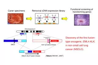
Dynamic Tests of Field Specimens Puneet Agarwal, Asli Kurtulus,Farn-Yuh Menq, and Sharon Wood Department of Civil Engineering University of Texas at Austin
Test Specimens 6'-0" 3'-0" 6'-3" 6'-3" Bent 2 Bent 1
Terminology Longitudinal Response of Bridge Transverse Response of Bridge
Scope of Presentation • Response of Bent 2 (short bent) is summarized. • Types of dynamic excitation: • Structural excitation using modal hammer • Ground excitation using T-Rex • Structural excitation using Thumper • Linear and nonlinear response was observed.
Austin Weather 120 6 Daily High Temperature 100 5 80 4 Daily Low Temperature 60 3 Temperature, degree F Rainfall Since 1 June 2005, in. Dates of Tests 40 2 20 1 Cumulative Rainfall 0 0 6/1/2005 6/8/2005 6/15/2005 6/22/2005 6/29/2005 7/6/2005 7/13/2005 7/20/2005 7/27/2005 8/3/2005
Instrumentation • Bent Cap • Two, 3D accelerometers • Two sets of three geophones • Columns • Strain gages • 1D accelerometers at three levels • Shafts • Strain gages • Two sets of three geophones in each shaft • Soil • One set of three geophones at ground surface
Modal Hammer • Essentially free-vibration response. • Very low levels of excitation. • Accelerometers and geophones captured response. • Strain gages exhibited only noise.
Modal Hammer f = 16.6 Hz = 6.1% 0.1 0.05 Longitudinal Acceleration (g) 0 -0.05 -0.1 0 0.5 1 1.5 Time (sec)
Modal Hammer Longitudinal Response 1.0 0.9 f = 16.6 Hz 0.8 0.7 0.6 Power Density 0.5 0.4 0.3 0.2 0.1 0.0 0 10 20 30 40 50 Frequency (Hz)
Harmonic Excitation • Stepped Sine • Sufficient cycles to achieve steady-state response at each frequency increment. • Duration of tests ranged from 2 to 10 minutes. • Chirp • Duration of tests ranged from 10 to 30 seconds. • Fixed Sine • Excitation at natural frequency observed during stepped sine tests.
T-Rex – Longitudinal Excitation Stepped Sine: 20-10 Hz 0.8 0.6 0.4 0.2 Longitudinal acceleration (g) 0 -0.2 -0.4 -0.6 -0.8 0 50 100 150 200 Time (sec) T-Rex is 25.3 ft from Bent 2 (Position 3)
T-Rex – Longitudinal Excitation Stepped Sine: 20-10 Hz 0.8 0.6 0.4 0.2 Transverse acceleration (g) 0 -0.2 -0.4 -0.6 -0.8 0 50 100 150 200 Time (sec) T-Rex is 25.3 ft from Bent 2 (Position 3)
T-Rex – Stepped Sine (20 – 10 Hz) Longitudinal Response 1.0 0.9 f = 14.6 Hz 0.8 0.7 0.6 Power Density 0.5 0.4 0.3 0.2 0.1 0.0 5 10 15 20 25 Frequency (Hz) T-Rex is 25.3 ft from Bent 2 (Position 3)
N S W T-Rex – Fixed Sine (15 Hz) Longitudinal Response of Column 2N 4 2 0 N W E -2 Distance from Ground Surface (ft) S -4 -6 Direction ofMotion -8 -10 -20 -15 -10 -5 0 5 10 15 Range of Measured Strains (microstrain) T-Rex is 25.3 ft from Bent 2 (Position 3)
Thumper – Longitudinal Excitation Stepped Sine: 20-5 Hz 30% of Peak Force 0.5 Longitudinal acceleration (g) 0 -0.5 0 20 40 60 80 100 120 140 160 Time (sec)
Thumper – Stepped Sine Longitudinal Response 30% of Peak Force 1.0 0.8 f = 12.6 Hz 0.6 Power Density 0.4 0.2 0 5 10 15 20 25 Frequency (Hz)
Longitudinal Response Transverse Response Frequency Response 35 30.0 30 25 23.0 20.5 20 Predominant Frequency, Hz 16.6 14.6 15 12.6 10 5 0 Thumper Modal Hammer T-Rex
Thumper – Longitudinal Excitation Stepped Sine: 12-5 Hz 80% of Peak Force 1.5 1.0 0.5 0 Longitudinal acceleration (g) -0.5 -1.0 -1.5 0 100 200 300 400 500 Time (sec)
Thumper – Stepped Sine Longitudinal Response 80% of Peak Force 1.0 f varies during test 0.8 0.6 Power Density 0.4 0.2 0 5 6 7 8 9 10 11 12 Frequency (Hz)
Longitudinal Response 20 Range of Nonlinear Response 16.6 15 12.6 11.7 – 12.0 10.9 8.2 – 9.5 10 Predominant Frequency, Hz 7.6 – 8.2 5 0 Modal Hammer 30% 60% 80% 100% Modal Hammer % of Peak Force using Thumper
Thumper – Longitudinal Excitation Gaps were observed at the shaft/soil interface.
S E W Thumper – Fixed Sine (9.5 Hz) Longitudinal Response of Column 2N 4 2 0 N W E -2 Distance from Ground Surface (ft) S -4 -6 Direction ofMotion -8 -80 -60 -40 -20 0 20 40 60 80 Range of Measured Strains (microstrain) 70% of Peak Force
Summary • Only a cursory review of the data has been completed. • Both bents experienced nonlinear response when excited using Thumper. • Soil gapping was observed. • Extent of concrete cracking is not known. • Static pull-over tests will be conducted after thorough review of the data. • Response of top 6 to 12 in. of soil is sensitive to moisture content.