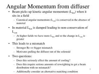
Angular Momentum from diffuser
This study explores the interaction of kinetic and canonical angular momentum within particle beams traveling through a material diffuser. It evaluates how changes in momentum affect beam distribution, cooling efficiency, and angular momentum conservation. Utilizing Monte Carlo simulations, we assess the influence of beamline design and energy spread on angular momentum, ultimately identifying mismatches that may hinder cooling performance. Options to mitigate these effects through careful tuning of parameters are also discussed, revealing the essential role of angular momentum in optimizing beam dynamics.

Angular Momentum from diffuser
E N D
Presentation Transcript
Angular Momentum from diffuser • Beam picks up kinetic angular momentum (Lkin) when it sits in a field • Canonical angular momentum (Lcan) is conserved in the absence of material • In material Lkin is damped leading to non-conservation of Lcan • At higher fields we have more Lkin and so the change in Lcan is greater • This leads to a mismatch • Stronger Bz => bigger mismatch • Motivates pulling the diffuser out of the solenoid • Two questions: • Does this seriously effect the amount of cooling? • Does this require serious amounts of reweighting to get a beam distribution with no mismatch? • Additionally consider an alternative matching condition
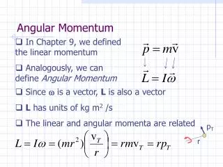
Change in Angular Momentum • Kinetic angular momentum given by Lkin = <xpy - ypx> • In a material change in angular momentum given by dLkin/Lkin ~ dpz/pz • Thin foil approximation • Monte Carlo (ICOOL) shows this is reasonably accurate • dLkin/Lkin in black, dpz/pz in grey • The usual 4 T, 333 mm, 200 MeV, 6 pi beam
DLkin from MICE diffuser • Without knowing the precise beamline design we can make an estimate for the diffuser thicknesses • Assume beamline produces roughly 2 p beam • Expect this to be good to ~10% • Gives lead thicknesses: • Gives dLkin/Lkin:
Effect on beta function • Introducing angular momentum will knock the beta function off • 10,000 muons, no energy spread/absorbers/rf/windows/scifi in these plots • Black plot shows beam with “normal” beta function • Red plot shows beam with mismatch that would be induced by a material • So take dLkin/Lkin=0.1 but keep s(x), s(x’) the same • Blue plot shows a slightly different beam matched with the Lcantaken into account • Take out some of the transverse momentum spread
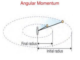
“Rematching” • Define matched covariance matrix by • And use • When I go through a diffuser g doesn’t change • If I want a beam with s(x) constant I have to be careful to choose s(px) with this L dependence • L is basically the canonical angular momentum i.e. • L = 0 w/o diffuser, <~ 0.1 with diffuser (depending on thickness)
Angular Momentum • Kinetic angular momentum varies wildly • The three plots that vary between +/- 3000 mm MeV/c are kinetic angular momentum • Canonical angular momentum is really conserved very well • Blue and red plots have non-zero canonical angular momentum • Again blue plot has been rematched to account for the Lcan • Black plot is again for standard solution with Lcan= 0 Lcan Lkin
Full Cooling Channel • Go on to consider MICE VI with absorbers and RF • No SciFi/detectors, still 10,000 events • Energy looks spot on • Slight mismatch induced by the momentum change even in case of Lcan=0 • Black is Lcan= 0 • Red has Lcan~0.1Lkin in the tracker • Blue has Lcan~0.1Lkin but rematched
Effect on Cooling • Slightly worse performance from the matched channel with angular momentum vs standard channel • Slightly better performance from the unmatched channel with angular momentum • But higher initial emittance • Regardless, the change in cooling performance from this effect (i.e. de/e) ~ 5% • This is well within specification (Perhaps beyond limits of statistics)
Phase Space Density • Phase space density contours in x-py phase space • 6 p beams but density scales • Looks like any reduction in phase space density will be a tweak
Underdensity Due to Lkin • This is [nLkin=0.1(mu) - ndesign(mu)]/ndesign(mu) in x-py phase space • Left is for unmatched beam • Right is for rematched beam • Black contours are phase space density contours for the ideal beam • Only underdensities are shown • Depletion in the fringes • Low statistics in this region (1000000 mu total) • Compared to the gain in rate through quad aperture, this is not an issue
Effect of Energy Spread on Cooling • Beta function for several different beams • Black has 1 MeV energy spread • Red has 25 MeV energy spread • Blue has 25 MeV energy spread and tracking in ICOOL • Green has 25 MeV energy spread and RF is at 40 degrees • Left hand plot has no RF/Absorbers, RH has full cooling
Transverse Emittance 25 MeV/RF 40o • Non-linear effects dominate with a small NuFact energy spread • Typical NuFact dE ~ 25-100 MeV • No cooling!? • Note blue & red have input beam but with different scaping (~1-5%) • In ICOOL I killed particles at r>250 mm • Did it properly in G4MICE 25 MeV/G4MICE 25 MeV/ICOOL 25 MeV/RF 0o 1 MeV 1 MeV
Longitudinal Phase Space Running on-crest Running at 400 • Longitudinal phase space at z = 2020.5 (centre of RF-8) • Note energy scale of RF bucket/Contours of Hamiltonian