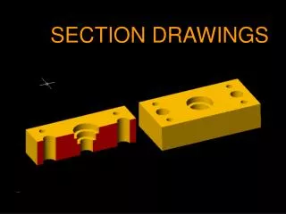
SECTION DRAWINGS
SECTION DRAWINGS. SECTION DRAWINGS. A section drawing shows detail on the inside of an object by cutting away part of the object. FULL SECTION. Q: Why do we call this a “Full” section?. FULL SECTION. A: The cutting plane line cuts through the entire length, height, or width. .

SECTION DRAWINGS
E N D
Presentation Transcript
SECTION DRAWINGS A section drawing shows detail on the inside of an object by cutting away part of the object.
FULL SECTION Q: Why do we call this a “Full” section?
FULL SECTION A: The cutting plane line cuts through the entire length, height, or width.
CUTTING PLANE LINES • Cutting plane lines mark the point at which the object is to be cut apart (wide dashed line .7mm thick). Sight lines point to the part of the object that is to be kept. CUTTING PLANE LINE SIGHT LINE
HATCHING Hatching is used to show where the object has been cut. In other words, if the part was cut with a saw, the hatching would represent where the saw actually touched the object as it was being cut. Hatch lines (.3mm) The pattern of the hatching used represents different types of materials. In the case above, a generic hatch has been used. This generic hatch is sometimes used to represent iron or steel.Hatch lines should match the color of the cutting plane line.
FULL SECTION No hidden lines on the sectional portion of a view
HALF SECTION Q: Why do we call this a “HALF” section?
HALF SECTION A: The cutting plane line cuts through only “Half” the length, height, or width of the object.
HALF SECTION This line divides the object so the sectioned portion and the non-sectioned portion can be defined.
OFFSET SECTION Offset sections allow one cutting plane line to transect multiple areas of a part. This reduces the amount of work needed to complete a drawing.
OFFSET SECTION Notice that there isn’t a line added to show where the offset portion of the cutting plane line changes direction.
BROKEN-OUT SECTION Notice that there isn’t a cutting plane line on this style of section drawing. Instead, a broken-out section line is used. (.7mm line)This style is used when a part is fairly symmetrical.
REVOLVED SECTION A revolved section is used to show the profile of a part in another view.In this case an “I” beam is shown from an angle that emphasizes its length. By breaking-out the center area and placing a side view in-line with the view, a sense of what this part actually looks like is better communicated.
BREAK LINES Break Lines (.3mm) Break lines are used when a long object that would otherwise not fit on a standard sized drawing is shortened. This can only be done on an object that is very regular. The picture above is of an “I” beam that is over 10’ long. It has been shortened using break lines so it can fit on an A-sized sheet of paper.