Hydraulic and Pneumatic Transmission
240 likes | 1.29k Vues
Hydraulic and Pneumatic Transmission. Chapter 1 Introduction to fluid power. Objectives: The purpose of this chapter is to describe: 1. Operation of hydraulic systems. 2. P ower elments, actuators, control components and Ancillary components .

Hydraulic and Pneumatic Transmission
E N D
Presentation Transcript
Chapter 1 Introduction to fluid power Objectives: The purpose of this chapter is to describe: 1. Operation of hydraulic systems. 2. Power elments, actuators, control components and Ancillary components. 3. fluid power diagram and symbols Upon completing this chapter, you should be able to: 1. Explain the operation of the various types of elements. 2. Identify the graphical symbols used for elements. 3. Understand the advantages and disadvantages of fluid power.
1.1 Transmission and transmission classification 1.1.1 Transmission A whole machine consists of a prime mover, a transmission section, a control section and a end-use device(working machine). The commonly used prime movers are electric motors, gasoline engines and diesel engines. 1.1.2 classification According to working media, the transmission mechanism can be classified as mechanical transmission, electric transmission and fluid transmission.
1.1 Transmission and transmission classification 1.1.3 FLUID POWER DEFINITION Fluid power is that energy transmitted and controlled by means of a pressurized fluid, either liquid or gas. The fluid transmission can be classified as hydrostatics transmission, hydrodynamics transmission, pneumatics transmission and viscosity transmission. Fluid power Hydraulic transmission Hydrostatic transmission Hydrodynamic transmission 1 Several words: 2 History of fluid power In the seventeen century, Pascal put forward the principle of fluid power In the eighteen century,the first press was manufactured
1.1 Transmission and transmission classification Before electrical power was developed , fluid power had being used to drive hydraulic equipment such as cranes, presses, winches, extruding machines, hydraulic jacks, shearing machines, and riveting machines. The modern era of fluid power is considered to have begun in 1906 when a hydraulic system was used for elevating and controlling guns on the battleship USS Virginia. During and after World War II the aviation and aerospace industry provided the impetus for many advances in fluid power technology . Today fluid power is used extensively in practically every branch of industry.
1.2 Theory of hydraulics and hydraulic system 1.2.1 Theory of hydraulics Figure1.1 Principle of operation of grinding machine’s hydraulic system 1-tank; 2-filter; 3,12,14-return line; 4-pump; 5-spring; 6-steel ball; 7-relive valve; 8,10-pressure line; 9-manually actuated directional control valve ; 11,16-hand lever; 13-throttle valve; 15-directional valve; 17-piston; 18-cylinder; 19-work table.
1→2→4→9→13→15 → 18(left) • 18(right)→15→1 • The work table moves to right. (b)1→2→4→9→13→15 → 18(right) 18(left)→15→1 The work table moves to left. (c)1→2→4→9→1 The work table stops. The pump unloads Valve 13—throttle valve, which is used for speed control. Valve 5—relive valve, which is used to maintain the system pressure constant.
1.2 Theory of hydraulics and hydraulic system 1.2. 2 COMPONENTS OF HYDRAULIC SYSTEM (1) A power component(pump) which forces the liquid through the system, and converts mechanical power to fluid power. (2)Actuators (Cylinders or motors) which convert fluid power to linear or rotary mechanical power. (3)Control components : including valves, which control the direction, pressure and rate of flow. Directional valve 15 is a control component. (4)Ancillary hydraulic components: Filters, regulators, pipes, reservoirs, etc.
check valve relieve valve cylinder pump motor 1.2 Theory of hydraulics and hydraulic system 1.2.3 fluid power diagram and symbols
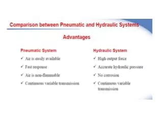
1.3 Advantage and disadvantage of fluid power 1.3.1 The advantages of fluid power (1) High horsepower, low weight ratio. Hydraulic components are compact and lightweight . (2)Easy, accurate controlling ,reversible, infinitely variable speed and load control completely automatic operations. (3)Accurate position control for linear and rotary elements, and variable speed control. (4)Power linkage where kinematic linkage is impractical, convenient method of power transmission over long distance. (5)Reduction of wear by the self-lubrication action of the transmission medium.
1.3 Advantage and disadvantage of fluid power (6) simplicity, safety, great flexibility, reliability and economy. (7) Standardization. The fluid power industry has established design and performance standards for hydraulic and pneumatic products. 1.3.2 Some of the major disadvantages of hydraulic systems (1) Impairment of system operation by contamination (2) Hydraulic fluid leakage (3) Fire hazards with flammable hydraulic fluids (4) Hydraulic lines can burst, possibly resulting in injuries to people due to high-speed oil jets and flying pieces of metal, if proper design is not implemented. (5) Adequate oil filtration must be maintained