Games Development 1 Camera Projection / Picking
Games Development 1 Camera Projection / Picking. CO3301 Week 8. Today’s Lecture. World / View Matrices Recap Projection Maths Pixel from World-Space Vertex World Space Ray from Pixel

Games Development 1 Camera Projection / Picking
E N D
Presentation Transcript
Games Development 1Camera Projection / Picking CO3301 Week 8
Today’s Lecture • World / View Matrices Recap • Projection Maths • Pixel from World-Space Vertex • World Space Ray from Pixel Note: Formulae from this lecture are not examinable. However, discussion of the general process may be expected
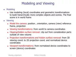
Recap: Model Space • An entity’s mesh is defined in its own local coordinate system - model space • Each entity instance is positioned with a matrix • Transforming it from model space into world space • This is the world matrix
Recap: World to Camera Space • Next we consider how the entities are positioned and oriented relative to the camera • Convert the models from world space into camera space • The scene as viewed from camera’s position • This transformation is done with the view matrix
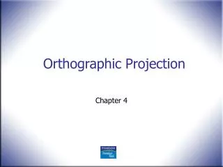
Camera to Viewport Space • Finally project the camera space entities into 2D • The 3D vertices are projected to camera position • Assume the viewport is an actual rectangle in the scene • Calculate where the rays hit the viewport = 2D geometry • This is done (in part) with the projection matrix
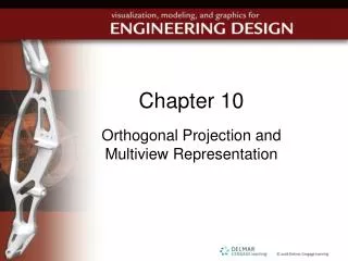
Projection Details • Cameras have internal settings: • Field of view (fov) • Clip distances – near and far (zn , zf) • Near clip distance is from camera position to viewport • Where the geometry “slices” through the viewport • Far clip distance is furthest that we can see • fov is similar to selection of wide angle or zoom lens • fov can be different for width and height – fovx & fovy
Projecting a Vertex • Consider projection of a 3D vertex (x, y, z) from camera space into 2D • Call 2D viewport coords (xv, yv) • y values not shown on diagram • Calculate using similar triangles: x / z= xv / zn Similarly y / z= yv / zn • So: xv= xzn / z &yv= yzn / z(1) • Now have 2D coordinates, but still in world/camera space units
Actual Size of Viewport • The 2D point (xv, yv) calculated above is still measured in world units • The viewport (part of the camera) has a physical presence in the world • Calculate its physical dimensions to help convert this 2D point to pixel units • Use camera settings to calculate viewport width & height: wv& hv tan(fovx/2) = (wv / 2) /zn so wv = 2zntan(fovx / 2) (2) hv = 2zntan(fovy / 2)
Converting to Viewport Space • First convert 2D point to viewport space before calculating pixel coordinates • In viewport space, on-screen coordinates range from –1 to 1 • Independent of viewport resolution • Divide 2D coords from (1) by physical viewport dimensions (2) to get viewport space point (xn, yn) xn = xv / (wv/2) = 2xv / wv(3) yn = yv / (hv/2) = 2yv / hv
Combining Steps • Started with a 3D camera space point (x, y, z) • Have showed three steps to get a resolution-independent 2D viewport space point (xn, yn) • Combining and simplifying the 3 steps gives: xn = x / (z tan(fovx / 2)) yn = y / (z tan(fovy / 2)) • This is the perspective projection (division by tan) and perspective divide (division by z) • In the rendering pipeline, the projection step is performed by the projection matrix • We haven’t previously looked at its operation
Perspective Projection Matrix • This is a typical perspective projection matrix: • Other (e.g. non-perspective) types are possible • Apply this to a camera space point(x,y,z): • Note the 4th (w) component becomes the original z value
After the Projection Matrix • Note how the x and y coordinate are similar to the projection equations we manually derived • Final step is to divide the x, y and z coordinates by the original camera-space z • The perspective divide mentioned earlier • The w component is used as it has the original z value • Note that the d value (in the z component) is also divided, leaving it in the range 0 to 1 • This is the value used for the depth buffer • Explaining why our 2D vertices have 4 components: 2D x & y, depth buffer value (in z) and original camera space z (in w) • In the rendering pipeline, the projection matrix is usually applied in the vertex shader • Perspective divide occurs after shaders (in hardware)
Converting to Pixels • Finally map the coordinates (xn, yn) from range -1 to 1 to final pixel coordinates (xp, yp) • If the viewport width & height (in pixels) are wp & hp then xp= wp (xn + 1)/2 yp= hp (1 - yn)/2 • Map to 0=>1 range then scale to viewport pixel dimensions • Second formula also flips the Y axis (viewport Y is down) • This usually occurs in hardware
Picking • Sometimes we need to manually perform the projection process: • To find the pixel for a particular 3D point • E.g. To draw text/sprites in same place as a 3D model • E.g. To find 2D coordinate of portal vertices • Or perform the process in reverse: • Each 2D pixel corresponds to a ray in 3D space (refer to the projection diagram) • Finding and working with this ray is called picking • E.g. to find the 3D object under the mouse • The algorithms for both follow – they are derived from the previous slides
1) Pixel from World-Space Vertex • Start with world space vertex P • Ensure it has a 4th component w = 1.0f • Multiply this vertex by combined view / projection matrix to give projected 2D point Q • If Q.w < 0 then the vertex is behind us, discard • Otherwise do perspective divide: Q.x /= Q.w and Q.y /= Q.w • Finally, scale to pixel coordinates X, Y: X = (Q.x + 1) * (ViewportWidth / 2) Y = (1 - Q.y) * (ViewportHeight / 2) • Use to draw text/sprites in same place as 3D entity
2a) World-Space Point From Pixel • Given pixel coordinates (X, Y), first convert to projected 2D point Q: Q.x = X / (ViewportWidth / 2) - 1 Q.y = 1 – Y / (ViewportHeight / 2) • We will calculate a result world-space point that is exactly on the clip plane, so: Q.w = Zn (the near clipping distance) Q.z = 0 (the closest depth buffer value) • Undo the perspective divide: Q.x *= Q.w, Q.y *= Q.w and Q.z *= Q.w • Multiply this vertex by the inverse of thecombined view / projection matrix to give final 3D point
2b) World-Space Ray From Pixel • The calculation above generates a world space point exactly on the near clip plane • As near to the camera as possible • More frequently want a ray • A line projecting from a point in a given direction • Ray start point is either the calculated point, or the camera position • Ray direction is (calculated point – camera position) • Cast ray through the scene to find nearest target • Can use space partitions to help with this task