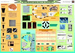
Tomographic Imaging
Tomographic Imaging. SPECT PET Hybrid. Spect. Conventional, Planar Imaging. Tomographic Imaging. Series of Projection images. Camera head(s) rotate about patient 360 o for most scans 180 o for cardiac scans Continuous acquisition or Step & Shoot Projection images acquired


Tomographic Imaging
E N D
Presentation Transcript
Tomographic Imaging SPECT PET Hybrid
Conventional, Planar Imaging Tomographic Imaging Series of Projection images
Camera head(s) rotate about patient • 360o for most scans • 180o for cardiac scans • Continuous acquisition or Step & Shoot • Projection images acquired • Images reconstructed • Filtered Backprojection • Direct Fourier Transform • Iterative • Multi-slice imaging Data Acquisition
Myocardial perfusion studies are acquired with 180oarc. Projection images from opposite 180o have poor spatial resolution & contrast due to greater distance & attenuation. Cardiac Scan
A dual-headed gamma camera system (top). • Note that the camera heads can be placed in different orientations to provide 2 simultaneous views of an organ or the body (bottom). • Typically 180° for whole body SPECT, 90° for cardiac imaging • Sensitivity ↑ • 2 angular projections acquired simultaneously 2-fold total # counts • OR • Same # of counts acquired in ½ time Multi-Head SPECT Systems
2-D intensity display of set of projection profiles (sinogram) Each row in display corresponds to individual projection profile, sequentially displayed from top to bottom. Point source of radioactivity traces out a sinusoidal path in the sinogram Image Reconstruction
Computer-simulation phantom B. Sinogram of simulated data for a scan of the phantom C.Image for simple backprojection of data from 256 projection angles. 1/r blurring is apparent in the object, and edge details are lost. 1/r Blurring
Ideal Ramp Filter Ramp Filters w/ Roll-Off Statistical noise (random nature of decay & photon interactions) dominates high frequencies roll-off will smooth image Removes 1/r blurring, sharpening image detail Amplifies high frequency noise Filter Kernels
More computationally intense than FBP • Requires > 1 iteration / image • Each iteration ≈ 1 FBP • Algorithms often incorporate characteristics of imaging device • Collimator & object scatter • System geometry • Finite detector resolution Iterative Reconstruction
# of Angular Samples Linear Sampling of Projections Sampling Effects Nviews≥ π FOV/(2Δr ) Δr (Sampling Interval) ≤ FWHM/3
Effects of angular sampling range on images of a computer-simulation phantom. Images obtained by sampling over 45°, 90°, 135°, and 180°. Sampling over an interval of less than 180° distorts the shape of the objects and creates artifacts Sampling Coverage
Effects of missing projection elements on reconstructed image. Left, Sinogram of computer-simulation phantom. Right, Reconstructed image. Detector Failure
Planar Imaging Tomographic Imaging SNR <Npixel> = average # counts recorded / reconstructed pixel npixels = total # of pixels • SNR • Npixel = # counts recorded for that pixel Stronger requirements on counting statistics for tomographic imaging as compared with planar imaging to achieve same level of SNR SNR Comparison
Planar Imaging Tomographic Imaging CNR SNRpixel |Cl| = Contrast of lesion nl= # pixels occupied by lesion SNRpixel↓ as compared to planar imaging Low-contrast lesion contrast ↑ as compared w/ planar imaging • CNR • |Cl| = Absolute contrast of lesion • = • Rcounting rate over lesion • R0 = counting rate over background • dl = Diameter of lesion • ID0 = Background info. density (cts/cm2) For the same level of object contrast & total # of image counts (in absence of distance & attenuation effects), no intrinsic difference in CNR between planar & tomographic imaging CNR Comparison
Detecting low-contrast lesions • Ability to remove confusing overlying structures that interfere w/ lesion detectability • e.g. ribs overlying lesion in lungs • Lesion shape & borders also become clearer • Does not improve detectability of lesions by ↑ CNR • More accurate determination of radioactivity concentrations in particular tissue volume Tomographic Imaging Advantages
Thoracic phantom images ↑Contrast & ↑visibility when overlying activity removed in SPECT Planar Vs. SPECT
Actual LOR resembles diverging cone rather than cylinder • Signal recorded not exactly proportional to total activity w/in LOR • Signal from activity closer to detector more heavily weighted than deeper lying activity due to attenuation of overlying tissue • Activity outside LOR contributes to signal • Crosstalk due to scattered radiation • Septal penetration through collimator • Most of discrepancies from ideal vary w/ γ-ray energy • Lead to artifacts & can seriously degrade image quality SPECT Challenges
Volumes of tissue viewed by a collimator hole at 2 different angles separated by 180°. Differences in the volumes viewed results in different projections from the 2 viewing angles Divergence of Response Profile
Attenuation leads to further differences in these two projections, emphasizing activity that is close to the gamma camera compared with activity further away that has to penetrate more tissue to reach the gamma camera. Values are shown for the attenuation of the 140-keV γ rays from 99mTc in water Attenuation Effects
Response profiles vs. source depth for single view projection of line source in air & H20 AIR: Degradation of spatial resolution w/ distance from collimator H20: Degradation due to distance & attenuation 2 opposing view projections of line source in air & water arithmetically averaged AIR: No degradation w/ distance H20: Only degradation due to attenuation 2 opposing view projections of line source in air & water geometrically averaged AIR: No degradation w/ distance H20: No degradation w/ distance Conjugate Counting
If attenuation coefficient constant throughout tissue volume (reasonable assumption in brain, abdomen) If attenuation coefficient not constant throughout tissue volume (reasonable assumption in thorax, pelvis)Transmission scan Flood source Line source Attenuation Correction
Attenuation map of the thorax reconstructed from the reference and transmission scans obtained with a moving line transmission source Reference Scan: 1stscan acquired w/ no object in FOV Transmission Scan: 2ndscan acquired w/ object of interest in FOV Attenuation Map
Dual energy windows used to simultaneously acquire SPECT & transmission scans Patient equivalent phantom scanned to acquire scatter distribution in projections Scatter Correction
Each cylinder contains same concentration of radionuclide, but w/ ↓ diameter For sources/volume > 2 x FWHM, image intensity reflects both the amount & concentration of activity w/in volume For smaller objects that only partially fill voxel, total amount of activity still correct, but intensities of pixel no longer reflect concentration of activity Spillover: when ROI has low tracer accumulation relative to surrounding tissues activity from these areas spills over to ROI Partial Volume Effects Results in ↓ contrast & under or over-estimation of tracer concentrations
Parallel Hole Fan Beam SPECT Collimator Design
Co 57 line sources water • In general the spatial resolution in SPECT is slightly worse than in planar imaging. • Camera head farther from patient • Spatial filtering used to reduce noise reduces resolution • Short time/view lower resolution collimator to obtain adequate numbers of counts Spatial Resolution
Planar • Radioactivity in tissue in front of & behind tissue/organ of interest ↓ contrast • Non-uniform pattern of radioactivity superimposes on activity distribution of tissue of interest • Structural noise SPECT • ↑ contrast& ↓ structural noise by eliminating counts from activity on overlapping structures • If iterative reconstruction implemented: • partially compensate for effects of scattering photons in patient • collimator effects • ↓ spatial resolution with ↑ distance from camera • septal penetration • When attenuation is measured with sealed source or CT data, can also partially correct for patient attenuation SPECT vs. Planar
X & Y Magnification Factors • Multi-Energy Spatial Registration • Center of Rotation • Mechanical COR must coincide w/ COR defined for each projection • If detector sags/wobbles as it rotates, artifacts result • Additional blurring or ring artifacts • Uniformity • Even very small non-uniformities can lead to major artifacts unlike planar imaging) • Rings or arcs in images • Flood field uniformities <1% desirable • To achieve 1% uncertainty, Poisson stats dictate 10,000 counts per pixel • For 64x64 matrix ~ 41 million counts • Camera Head Tilt SPECT QC
SPECT Artifacts Attenuation Center of Rotation Uniformity Stray Magnetic Field Effects Motion
Portion of the imaging volume falls outside the gamma camera FOV during a portion of the acquisition arc. Truncation Artifact
Insufficient gamma camera uniformity Bulls Eye Ring Artifact
Ideally, the center of rotation is aligned with the center, in the x-direction, of each projection image. • Misalignment can be • Mechanical • Camera head not exactly centered in gantry • Electronic • Will cause loss of resolution in images • Point sources can appear as doughnuts COR Artifact
SPECT Applications Myocardial Perfusion Cerebral Perfusion Oncology Infection / Inflammation Liver & Kidney Function
Myocardial Perfusion • Assess CAD & heart muscle damage following infarct • Gated or Non-gated • Cerebral Perfusion • Cerebral vascular disease • Dementia • Seizure Disorders • Brain tumors • Psychiatric Disease • Oncology • Accumulation of cancer cells in both primary & metastatic lesions • Infection/Inflammation • Liver/Kidney Function Applications
SPECT images showing perfusion in the heart muscle of a normal adult using 99mTc-sestamibi as the radiopharmaceutical. The image volume has been re-sliced into 3 different orientations as indicated by the schematics on the left of each image row. SPECT data were acquired over 64 views with a data acquisition time of 20 sec/view. Images were reconstructed with filtered backprojection onto a 128 × 128 image array. Cardiac Perfusion
Transaxial SPECT images showing perfusion in the brain of a normal adult following injection of 890 MBq of 99mTc-HMPAO. Data were acquired on a triple-headed gamma camera with low-energy, high-resolution fan-beam collimators. One hundred twenty projection views were collected in 3-degree increments (40 views per camera head) with an imaging time of 40 sec/view. Total imaging time was approximately 30 minutes, with acquisition commencing 50 minutes after radiotracer injection. Brain Perfusion
Scintillation crystals coupled with PMTs in pulse mode • Signal characteristics identified: • Position in detector • Energy deposited • Energy discrimination used to reduce mispositioning due to scatter • Time of interaction • Coincidence detection Detectors
Emit light promptly (Small decay constant) • True coincidence distinguishable from random coincidence • Reduce dead time losses at high interaction rates • High linear attenuation coefficient for 511-keV γ • Max counting efficiency • High conversion efficiency • More precise event localization • Better energy discrimination Detector Characteristics
BGO being replaced by LSO, LYSO or GSO Comparison of Scintillators
Radioactive tracers manufactured to mimic naturally occurring substances already used by the body. As the body incorporates the radioactive tracers into its systems, PET scan can monitor their progress and examine specific bodily processes that use the tracer FDG