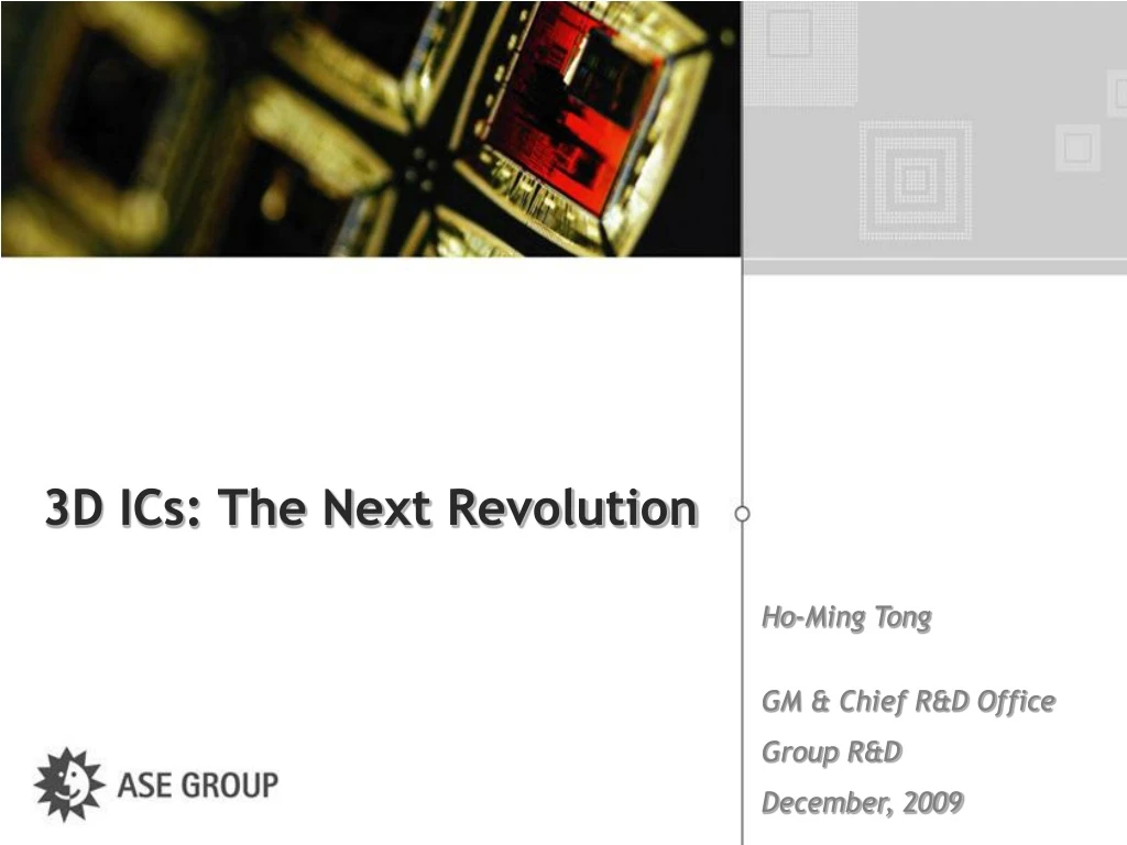
3D ICs: The Next Revolution
500 likes | 616 Vues
Explore the groundbreaking revolution of 3D IC technology, challenges, and opportunities, driven by Moore's Law and semiconductor advancements. Discover the evolving trends in package technology, co-design strategies, and the impact on IC, memory, and logic scaling. Dive into the fusion of ICTrends, performance improvements, power reduction, and multi-core innovations shaping the future of semiconductor design.

3D ICs: The Next Revolution
E N D
Presentation Transcript
3D ICs: The Next Revolution Ho-Ming Tong GM & Chief R&D Office Group R&D December, 2009
19th Century France First Republic Third Republic Second Republic Louis-Napoléon Bonaparte (Napoléon III) Napoléon Bonaparte (Napoléon Ier) Louis-Philippe Ier Charles X Louis XVIII 1800 1810 1820 1830 1840 1850 1860 1870 1880 1900 1900 Victor Hugo (1802-1885) • “You Can Resist An Invading Army; You Cannot Resist An Idea Whose Time Has Come,” • Victor Hugo, French Author of • The Hunchback of Notre Dame • Les Misérables
3D ICs: The Next Revolution • ICTrends • Package Trends • 2.5D IC Applications • 3D IC Challenges & Opportunities • IC-package-system Co-design
Moore’s Law Driving Semiconductor Source: Intel ftp://download.intel.com/research/silicon/Gordon_Moore_ISSCC_021003.pdf
(Atoms Don’t Scale) Planar CMOS Transistor Scaling Approaching Practical Limits Ref.: Chen (IBM ’09)
Performance Improvement At The Expense of Power 2.0 Perf / Watt (au) 130 nm 150 nm 1.7 Goal 250 nm 1.4 90 nm 1.1 65 nm 45 nm 350 nm 0.8 W. Haeosch et al IBM J. R & D. (2006) 0.5 10 100 1,000 Lg (nm) Disruptive Low-power & High Performance Technology Required
2009 2011 2013 2015 2017 CMOS Logic & Memory Scaling Continues Deep Submicron Nano Fines/Wires Deep Nano ~ Atomic Ref.: Jammy (SEMATECH ’09)
Semiconductor in Transition ‘12 ‘95 ‘00 ‘05 ‘06 ‘09 ‘10 ‘15 ‘20 ‘25 ‘30 ‘35 ‘13 DDR4 DDR3 DDR2 Source: Samsung
Multi-core Extends Performance As Clock Frequency Saturates Clock Speed (Arb.) Ref.: Shapiro (IBM ’09)
3D IC is Next Revolution inSemiconductor & Package Technology Roadmaps Better Performance • Massive Bandwidth • Reduced Interconnect Delays • Power Reduction • Higher Functionality/Space • Heterogeneous Integration Photonics Smaller Size MEMS • 3D Maximizes Space Utilization RF Memory Lower Cost CMOS • Lower Cost vs. Next-gen Device • Reuse of Proven SIP
FO-WLP SiP Heterogeneous Integration Heterogeneous Integration IC + Assembly Assembly + Substrate 3D SiP Evolution Finer Pitch FO-WLP WLCSP Wireless Proximity - Capacitive - Inductive Wirebond BGA FC BGA 3D IC 2.5D IC (Si Interposer) EPS Stacked Die PoP
2.5D IC Processor ELK/ULK Layers Rep or RDL Bump TSV Silicon Interposer Substrate BGA Ball ASE 2.5D & 3D ICs 3D IC Memory Bump Rep or RDL Processor TSV ELK/ULK Layers Substrate BGA Ball
Taipei: 100 Years Ago & Now 3D IC Building 101 2D IC
3D SiP Benchmarking: 2.5D IC Available Before 3D IC Process (Assy+Test) Performance EDA Supply Chain Stacked Die Fair PoP Fair Existing Infrastructure FO-WLP Fair 2.5D IC Good Now - ‘10 SoC Good 3D IC Excellent ’11 - ‘12 ‘11 ‘12 Year Ready by Year Ready
IC-package-system Compatibility Keyto 2.5D & 3D ICs Applications GPU, CPU, Chipset & FPGA 2.5 & 3D ICs w/ TSVs High Networking Memory Application Processor BT/WiFi Baseband ELK / ULK Wafers (≦ 45 nm Nodes) Chip Size PM Transceiver Peripheral I/O Controller PA Switch Discrete 200 300 500 600 100 400 High I/O
Front-end Middle-end Back-end = Front-end + Back-end Changing Supply Chains 2.5D IC (Si Interposer) 3D IC (Via First) TSV Fab + TSV Backside Grinding Backside Grinding Fab Bottom Side RDL Surface Treatment Rep RDL Top Side RDL + Micro-bump FC Bumping Micro-bump Die Stacking Die Stacking Assembly & Test Assembly & Test
2.5D IC: An Alternative to 3D IC Memory MEMS Processor RF Silicon Interposer
2.5 IC Enables Device Function Partitioning for Cost Performance RF Node 2 (> Node 1) BB Node 1 (= 28 nm) BB RF PMU PMU Node 3 (> Node 2) 28 nm (Single-chip Package) 2.5D IC Silicon Interposer
ASE 2.5D IC w/ IPD Inductor Resistor Capacitor Balun Balance Filter Diplexer Band Pass Filter
Si Interposer 2.5D IC Bridges The Interconnect Gap Between IC & Substrate High 40/40 µm 30/30 µm 20/20 µm 15/15 µm - 10/10 µm L/S Substrate Capabilities 85% 80~85% 65~75% <65% Yield* Package Cost (Excl. Die) FCCSP Assembly + Substrate Cost Substrate 2.5D IC Substrate Interposer 1+2+1 Cost Assembly Assembly 2 Layer Cost Node 1 > Node 2> Node 3> Node 4 Advanced Wafer Node * Base on The Best Substrate Source
3D IC Challenges & Opportunities: Cost is Everything Assembly Memory Metrology Bump Test TSV Processor ELK/ULK Layers Thermal Substrate Design System
2.5D & 3D ICs Revolutionize Existing Advanced Packaging Infrastructure ‘09 ‘10 ‘11 ‘12 ‘13 FAB Technology 45 nm 45 nm 32 nm 28 nm 28 nm 150 125 - 40 110 - 30 125 - 30 140 - 80 FC Bump Pitch (µm) µBump µFC µWLCSP µSiP D2D & D2W FC Assembly Substrate L/S (µm) 25/25 20/20 20/20 15/15 10/10 BackSide Wafer-level L/S (µm/µm) 15/15 10/10 6/6 6/6 6/6 > 100 70 < 50 50 80 Wafer Probing Pitch (µm)
Innovation Required to Reduce 3D IC Assembly Cost High Min Substrate Solutions Standard Reflow FC Bump Pitch Assembly Cost Pitch/Wafer Thickness 2.5D IC 3D IC TSV Micro-bump Pitch Thermal Compression Bonding Max 2007 2008 2009 2010 2011
Innovations in Metrology TSV High FC Bump Wirebond X-Ray Resolution 3D X-ray Computed Tomography IC Feature Size Small
3D IC Metrology Opportunities Microbump Joint (X-ray) Re-passivation/RDL (August) Memory TSV Depth (IR: FOGALE) TSV Depth (SAWLI: STIL) TSV CD (AVI: August) TSV Plating (X-ray: Dage) TSV Stop-on-metal (E-beam: N/A) X X X Processor X X X Rep/RDL (August) Interface Adhesion (SAT) Solder/Cu Pillar Joint (X-ray) Wafer-level Test (Probe Card) Gap Ready
Scrap or Barely Usable Scrap 3D IC Yield Y1 = Joint Yield Memory Y2 = Repassivation/RDL Yield Y3 = Interface Yield X X Y4 = TSV Yield X X Y5 = Interface Yield Processor X Y6 = Repassivation/RDL Yield ELK/ULK X RDL X Y7 = Joint Yield X Y8 = Joint Yield X Y9 = Substrate Yield X Y10 = Joint Yield
TSV Redundancy Improves Yield Electrical Redundancy Achieved by 7 Bars Refs.: (Samsung ’09) & Shapiro (IBM ’09)
RF MEMS Memory Logic Substrate 3D IC Test Challenges & Opportunities • Known Good Die • RF/At Speed Digital/IPD • Test Coverage • TSV Test • Finer Pitch (≦50 µm, Area Array) • Thin Wafer Handling (≦ 100 µm) • 3D IC Integrated Test • Test Access • System-level Test • Yield • Optimized Assembly & Test Flow • Test Cost • Cost Effective Test Refs.: Verigy, NXP, TI, & ASE Data
3D IC Equipment Readiness Ready for Prototyping Ready for Mass Production No Solution Yet Ready for Qualification
High Power Density Resolving 3D IC Thermal Challenges Through IC to System Co-design (Source: Intel) Packaging 3D IC System • 3D Floor Planning • Dynamic & Leakage • Power Management • Cooling Capacity • Space Constraint • Noise • Hot Spots • High Power Density • Micro-channel w/ Nanofluid • Nano Materials • 3D EDA Tool • Thin-film Thermo- • Electric Cooler (TFTEC) • Vapor chamber • Liquid Cooling • Thermo-Electric • Cooler (TEC) • Refrigeration • Cooling Challenges Test Possible Solutions • Test Socket / Chuck Design • Burn-in Oven Cooling Capacity • Liquid Cooling • Thermo-Electric Cooler (TEC)
New System Architecture Required for 3D IC Proliferation • Key: IC-package-system Co-design • System Cost • Software • Performance: Clock Feed & Power Feed • Function Partioning • Chip to Chip Interface Standardization • Supply Chain Complexity: Inventories, Liability & Shipment • Alternative Solutions • Test Coverage & Flow • Hot Issues: Memory Interface & 3D System Bus Standards Refs.: Laukkala & Kujala (Nokia) & Shapiro (IBM)
3D IC Integration Requires Concurrent IC – package - system Co-design for Yield & Reliability P24 System Partition Design Entry (RTL) Logic Synthesis (Gate Level Realization) Physical Implementation (Floor Plan / P&R) Chip Finishing (DRC/DFM) Chip Fabrication Chip Test IP Reuse Foundry TSV Design Reference Flow Design Entry (RTL) Logic Synthesis (Gate Level Realization) Physical Implementation (Floor Plan / P&R ) Chip Finishing (DRC/DFM) Chip Fabrication Chip Test System Architecture Planning & Spec Definition PKG Process Risk Assessment & Design Rule PKG Perf. Parameter Data base Package Design Assembly Tape Out 3D IC Integration Assembly & Test System Software & Firmware Development System Integration Design System Integration Test IC Design House Wafer foundry Assembly & Test System & Product
3D IC Concurrent Design Requires Modeling & Validation at Package & System Levels Thermal Management Via R, L, C Modeling
Ensuring Package-system Compatibility Besides Chip-package Compatibility + + =
2.5 IC Enables Device Function Partitioning for Cost Performance RF Node 2 (> Node 1) BB Node 1 (= 28 nm) BB RF PMU PMU Node 3 (> Node 2) 28 nm (Single-chip Package) 2.5D IC Silicon Interposer
Co-design Critical to Ensure Chip-package-system Compatibility for FCBGA No Longer Dumb Connector Si Die ELK/ULK ELK/ULK Layer Crack ! RDL Rep Underfill - Rep Delamination ! Bump IMC Crack ! Underfill Solder Bump Solder Mask Cu Pad BT Core
Co-design Also Crucial to 3D IC forChip-package-system Compatibility Front-end Memory Back Side Bump Middle-end Back Side Rep or RDL Processor Die w/ TSVs (Via Last) Front-end ELK/ULK Layers Middle-end Substrate Back-end 3D IC (Via First) Memory + Processor Stack
3D IC Co-design Challenges & Opportunities 3D IC RF MEMS Board Memory Analog Passives Controller Interposer + IPD Logic SOC Substrate
3D IC Applications Abound 2010 ~ 2020 (Driver: Better Life) 2020 ~ 2040 Now • Quantum Nucleonic • Biofuel • Biometics • Bionics: • - Robo Sapiens • - Cognitronics • - Genotyping • Frictionless Vehicles • Lab-on-a-chip • Molecular Sensor • Nonobots • Self-illuminating • Highway • Transportation • Drive to Autonomous Cars • Telematics Infrastructure • Medical Electronics • Imaging • Diagnostics & Therapy • Home Medical • Security • Video Analytics • Video Intelligence • Green Energy Harvesting • Macro: Solar,Wind & Wave • Micro: Piezoelectric, Kinetic & Thermoelectric • Thin Film Batteries • CMOS Image Sensor • Memory • SRAM/DRAM • NAND • Application Processor /Baseband • CPU • GPU • FPGA • MEMS …
3D IC Users in The Era of Heterogeneous Integration Package Level Package & Die Levels Package, Die & System Levels High High • FO-WLP • EPS • 2.5D IC • 3D IC • Flexible Circuit • MEMS • Opto • Wireless Proximity SiP More Than Moore Quantum Technology Component Density Transistor Density Brick Wall • Stacked Die • PoP • Molecular • Bio Silicon Technology SoC Feature Size System Component Density 45 nm 4 nm 1990 2000 2010 2020 2030 2040
Implanted Wireless Device World's First ‘Wireless' Pacemaker Talks to your Doctor Daily, Whether You Like It or Not (Though You Probably Do) by Joseph L. Flatley (8/’09)
Thank you for your listening www.aseglobal.com