GSI vacuum group
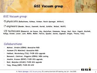
GSI vacuum group. Who we are: 5 physicists (Bellachioma, Kollmus, Krämer, Reich-Sprenger, Wilfert) 7 engineers (Bender, Bevcic, Kaminski, Kurdal, Schäfer, Welzel, Wolff)

GSI vacuum group
E N D
Presentation Transcript
GSI vacuum group • Who we are: • 5 physicists(Bellachioma, Kollmus, Krämer, Reich-Sprenger, Wilfert) • 7 engineers(Bender, Bevcic, Kaminski, Kurdal, Schäfer, Welzel, Wolff) • 23 technicans(Emmerich, de Cavaco, Gaj, Gustafson, Hammann, Herge, Heyl, Horn, Jagsch, Kischnik, Kolligs, Kredel, Leiser, Lück, Mühle, Müller, Norcia, Quador, Savino, Sigmund, Stagno, Thurau, Volz) • Responsible for: • operation and service of all GSI accelerator vacuum systems, • R&D on vacuum physics and techniques, • Design & Layout of new accelerator vacuum systems, • Installation & reconstruction of accelerator structures and experimental setups H. Reich-Sprenger, GSI Vacuum group, CERN, OLAV workshop (11./12.4.2005)
Overview • The existing GSI facility and its Future extension • SIS18 UHV Status / Upgrade • Ion Induced Desorption H. Reich-Sprenger, GSI Vacuum group, CERN, OLAV workshop (11./12.4.2005)
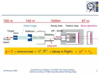
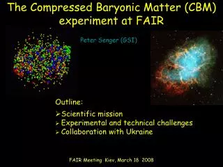
The GSI Future Accelerator Facility for Beams of Ions and Antiprotons (FAIR) • From protons to uranium • In future also antiprotons • 1 MeV/u to 2 GeV/u • In future up to 30 GeV/u • 109 to 1011 particles/cycle • In future 1012 particles/cycle • 0.1 Hz to 1 Hz Repetition rate • In future up to 3 Hz 100m Acceleration II III • Nuclear and Hadron Physics • Nuclear Chemistry • Atomic Physics • Material Science • Plasma Physics • Biophysics, Medical I Experiments H. Reich-Sprenger, GSI Vacuum group, CERN, OLAV workshop (11./12.4.2005)
The GSI Future Accelerator Facility for Beams of Ions and Antiprotons H. Reich-Sprenger, GSI Vacuum group, CERN, OLAV workshop (11./12.4.2005)
GSI International Accelerator FacilityUHV system requirements Due to ion beam lifetime requirements (e.g.: U28+ in SIS18): SIS18: bakeable p≈5·10-12 mbar ESR: bakeable p≈5·10-12 mbar SIS100: cold arcs T=7-20K bakeable straight sections T=300K p≈5·10-12 mbar SIS300: cold arcs T=4.2K bakeable straight sections T=300K p≈5·10-12 mbar NESR: p≈5·10-12 mbar HESR: p≤10-10 mbar RESR: p≤10-10 mbar CR: p≤10-9 mbar HEBL: length 2.5 km, 70% cold *all pressures: N2 equivalent SIS100/300 from SIS18 HESR CR RESR NESR H. Reich-Sprenger, GSI Vacuum group, CERN, OLAV workshop (11./12.4.2005)
The heavy ion synchrotron SIS 18 present status • 12 sectors each: • 18 m long • 200 mm • 4 TSP • 3 Ion pumps (triode type) • 1-2 extractor gauge • 2 single cryopumped collimators • 7 vacuum sectors • One pumping station with turbo molecular pump (rough pumping + bake-out) • 1 RGA H. Reich-Sprenger, GSI Vacuum group, CERN, OLAV workshop (11./12.4.2005)
High Ion Beam Intensity Operation of Medium Charged Heavy Ions influence of intensity on lifetime 8.75 MeV/u U28+ Desorption processes degenerate the residual gas pressure ( U28+ case ) Initiated by : • Systematic beam losses on acceptance limiting devices (septa) ( 8MeV/u < E <100MeV/u ) • Stripped beam ions ( 8MeV/u < E <100MeV/u ) • Ionized and accelerated residual gas ( E < keV) : minor effect • at “zero ion beam current”: lifetime could be increased up to 6s (first steps of UHV upgrade in 2003) • beam losses increase with number of injected ions • presently the maximum accelerated U28+ ion beam intensity is limited by dynamic UHV conditions H. Reich-Sprenger, GSI Vacuum group, CERN, OLAV workshop (11./12.4.2005)
SIS18 residual gas composition (10/2003)RGA spectra examples existing "micro-leaks"and contaminations Ar CxHy S03 total pressure: 3*10-12 mbar S08 total pressure: 6.8*10-11 mbar H. Reich-Sprenger, GSI Vacuum group, CERN, OLAV workshop (11./12.4.2005)
Requirements + Strategy for SIS18 UHV-Upgrade Beam lifetime has to be significantly larger than cycling time of the SIS18 (Lifetime of at least 10 seconds for all kinds of operation) Total pressure lower 1∙10-11 mbar with a small fraction of high Z gases even for highest beam intensities • optimized static conditions: • minimized outgassing rate by material and production control, cleaning, bakeout, quality control established, • removal of contaminations or "micro-leaks" measurements during shutdowns on TSP + SIP • efficient and distributed pumping NEG coating. • optimized dynamic conditions: • efficient ion beam loss control, • low desorption at localized ion beam losses Desorption / ERDA Experiments, • maximized local pumping speed at locations of ion beam loss collimation Desorption / ERDA. H. Reich-Sprenger, GSI Vacuum group, CERN, OLAV workshop (11./12.4.2005)
Beam Lifetime measurements 132Xe18+ (March 2005) SIS /ESR("zero" beam intensity) • Main Differences of SIS18 and ESR UHV system: • Argon partial pressure concentration: ESR < 1%, SIS > 2 % • bakeout ability: ESR >200°C, SIS18 ~ 180°C ESR 6.3.2005 H. Reich-Sprenger, GSI Vacuum group, CERN, OLAV workshop (11./12.4.2005)
Program for Optimized Static Conditions: H. Reich-Sprenger, GSI Vacuum group, CERN, OLAV workshop (11./12.4.2005)
Static Pressure Improvements by NEG coating • Remarks: • calculation fitted to measured Ptot and RGA locations in S03 • H2 and CO pumping speed (H2:0.05 ls-1cm-2; CO: 0.1 ls-1cm-2) for NEG coated chambers underastimated (has to be reduced by factor of 10 for H2 and by a factor of 50 for CO in VakTrac simulation due to calculation errors), • Total pressure will be dominated by CH4 after NEG coating minimzing the number of installed SIPs, changing SIP type?, H. Reich-Sprenger, GSI Vacuum group, CERN, OLAV workshop (11./12.4.2005)
Ion Beam Loss Induced Desorption:U28+ ion beam operation of SIS18(up to 1010 injected ions) SIS Extraction SIS Injection • Observations: • beam loss + pressure rises at all SIS sectors, • pressure rises in TK9, Scraper H. Reich-Sprenger, GSI Vacuum group, CERN, OLAV workshop (11./12.4.2005)
Desorption Processes in SIS18 vacuum chamber wall S: pumping speed/therm. desorption X septum or collimator X hloss X X UZ+ UZ+ UZ+ q e sX sloss X F50 Volt space charge potential X X X Xq+ UZ+q hX hloss beam loss induced desorption ion induced desorption desorption yield h: H. Reich-Sprenger, GSI Vacuum group, CERN, OLAV workshop (11./12.4.2005)
Experimental Setup for Ion Beam Induced Desorption Yield Measurements Experiments by: M. Bender (GSI) H. Kollmus (GSI) A. Krämer (GSI) E. Mahner (CERN) H. Reich-Sprenger, GSI Vacuum group, CERN, OLAV workshop (11./12.4.2005)
Partial Pressure Increase due to Ion Beam Induced Desorption 1.4MeV/u 1.8-3.1·109Pb27+ stainless steel 304 The measured ion current was corrected for the ionization probabilities of the different gases: H2: x2.3 CO: x0.95 CO2: x0.71 CH4: x0.625 Desorption dominated by H2 (87%) and CO (11%) H. Reich-Sprenger, GSI Vacuum group, CERN, OLAV workshop (11./12.4.2005)
Optimized Dynamic Conditions: • collimators at locations of known ion beam loss: • injection section / septum • extraction / septum • with integrated high pumping speed: • 2 cryopumps • NEG coated anti-chambers? • low desorption materials: • experiments at test bench with ion beam • distributed pumping speed: • NEG ? May/June 2003 March 2004 2006 ? since April 2003 final decision depends on desorption experiment results H. Reich-Sprenger, GSI Vacuum group, CERN, OLAV workshop (11./12.4.2005)