DC-DC Fundamentals
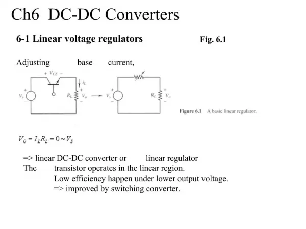
DC-DC Fundamentals. 1.4 Charge Pump Regulator. What is a Charge Pump Regulator?. The charge pump regulator is a kind of switching regulator that delivers power by only alternatively charging and discharging capacitors.

DC-DC Fundamentals
E N D
Presentation Transcript
DC-DC Fundamentals 1.4 Charge Pump Regulator
What is a Charge Pump Regulator? • The charge pump regulator is a kind of switching regulator that delivers power by only alternatively charging and discharging capacitors. • It’s suitable applications with low load current and moderate input to output voltage difference Q1 Q3 CF + VIN VCF + Q4 Q2 Io + Co Vo LOAD -
Pros and Cons Advantages Disadvantages • No inductor is needed, smaller size • Moderate Efficiency, higher than linear regulators • Vout can be higher or lower than Vin • Fewer components needed make the charge pump easier to design and lower cost • Switching produces higher output ripple & noise • The output current capacity is limited by the capacitors
How Does a Charge Pump Work? • The capacitors connection is altered by the switches so that the charge and discharge is controlled • Switches S1, S3 and S2, S4 are switching in complementary: • S1, S3 on, S2, S4 off, charging • S1, S3 off, S2, S4 on, discharging • By reversing the connections of the output to ground, the unity gain converter becomes negative gain inverter Unity gain Inverting gain
Voltage Doubler • The voltage doubler circuit shown below still has a single capacitor in the topology, only the connections are different • The switching of the four switches are still the same • S1, S3 on, S2, S4 off, gain phase • S1, S3 off, S2, S4 on, common phase • However, in the common phase, the input source is still connected to the capacitor: Vout = Vc + Vin = 2Vin Voltage Doubler By swapping Vin and Vout, the same doubler circuit will give half gain
More Gain Combinations • Include two capacitors in the charge pump, and many different gain can be generated by varying the connection combinations • The following figure shows some configuration of two capacitor connection and the resulting gain that can be achieved: Same common phase connection for all gains *Assuming C1 = C2
Charge Pump Regulation • By including a post regulator stage, the charge pump can achieve fine granular of the output voltage • Also, the switch impedance can be controlled to act effectively as a post regulator • Rout is the effective output impedance including the switch impedance Rsw, and the switched cap impedance (1/Fsw*Cf) • Fine adjustment can be accomplished by controlling Fsw or Rsw
Charge Pump Regulation • Control the frequency: Pulse-Frequency Modulation (PFM) • The output voltage is held constant by skipping unneeded pulses • Advantages: very low quiescent current, higher efficiency • Disadvantages: Higher output voltage ripple, frequency varies • Control the resistance: Constant-Frequency Regulation • Regulate the output by changing the resistance of the internal switches • Advantages: low voltage ripple, fixed frequency • Disadvantage: high quiescent current 8
Summary • Introduction to charge pump regulator • The operation and configuration of switching regulator • The charge pump regulation