DC TO DC CONVERSION (CHOPPER)
DC TO DC CONVERSION (CHOPPER). ET502 POWER ELECTRONICS. PUAN HJH HANIFAH BINTI JAMBARI. Contents:. Objectives Types of power electronics conversion Revise of RECTIFIER Chopper Definition Type of Chopper. Learning Objectives. After completing this class, the student

DC TO DC CONVERSION (CHOPPER)
E N D
Presentation Transcript
DC TO DC CONVERSION(CHOPPER) ET502 POWER ELECTRONICS PUAN HJH HANIFAH BINTI JAMBARI
Contents: • Objectives • Types of power electronics conversion • Revise of RECTIFIER • Chopper Definition • Type of Chopper
Learning Objectives After completing this class, the student should be able to: • Explain what the term chopper means • Lists on 4 types of DC – DC converter • Describe the basic operation of buck chopper • Describe the basic operation of boost chopper
Tasks of Power Electronics • AC –to- DC conversion - RECTIFIER • DC-to DC conversion - CHOPPER • DC-to-AC conversion - INVERTER • AC-to-AC conversion - CONTROLLER
RECTIFIER • RECTIFICATION - referring to conversion of ac voltage to dc voltage Vin Vout • TYPE OF RECTIFIER 1. Half bridge 2. Full Bridge -uncontrolled rectifier, semi-controlled rectifier and controlled rectifier
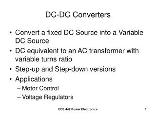
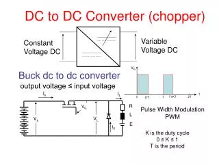
CHOPPER • DEFINITION: Converting the unregulated DC input (from rectifier) to a controlled DC output with a desired voltage level (regulated DC output). • In other words Chopper is used to obtain a variable DC voltage from a constant-voltage DC source using Power electronics semiconductor devices(SCR, Thyristor, GTO,IGBT, Mosfet, etc). • Basic block diagram• VacVdcVdc RECTIFIER CHOPPER M
TYPES OF SWITCH MODE DC-DC CONVERTERS There are basically four types of switch mode power converter. These are, • Buck Converter (Step Down Converter ) • Boost Converter ( Step up Converter ) • Buck Boost Converter ( step up/step down Converter ) and • Cuk Converter The first three converters operate with the help of inductive power transfer principle, whereas, the Cuk converter operates with capacitive power transfer principle. To page 10
APPLICATIONS: • Switched-mode power supply (SMPS)*, DC motor control speed, battery chargers, monorail system ,marine, industrial, transportation(hybrid car), mobile, and other applications. * Switch mode power supplies are high frequency dc to dc converters capable of stepping up and down the dc according need but are limited to low power applications in power supplies of computers, TVs, VCRs, and other electronic appliances.
1. Buck (step-down) converter • -The circuit is used to obtain low output • Voltage compared to the input voltage • O/put can be controlled • 0 < Vo < Vi
Buck converter:Circuit operation when switch is turned on (closed) • Diode is reversed biased. Switch conducts inductor current • This results in positive inductor voltage, i.e: • α= duty ratio 0< α < 1 • It causes linear increase in the inductor current Vo = V Vo = α V To Page 7
Buck converter:Circuit operation when switch is turned off (Opened) • Because of inductive energy storage, iL continues to flow. • Diode is forward biased • Current now flows through the diode and to the load for certain time until the energy store is zero.Therefore; Vo = VD = 0 V
If t = T, switch is closed again, this cycle is continuous until the power supply is not connected to the circuit • The load current was flow continuous with positive value • The output voltage consider as a chopper voltage with discontinuous mode • This buck converter only can produced positive output voltage and current.
ON and OFF switches can be controlled using α (constant switching) • Output Voltage can be calculated as below: Whereas, ton = time for chopper on T = time for one cycle( T = ton + toff) = duty ratio ( o < < 1) Vo =αV = ton x V T α α
Question • If the V is 10 V and the duty ratio is 0.5. Calculate the output voltage (Vo) • Given value of ton and toff are 0.8s and 0.2s respectively for buck chopper. Find the values of: a. time for on cycle (T) b. duty cycle, c. output voltage if the input voltage is 20V 3. Given T =1.5 s, Vo= 30V a. If Vi = 50, calculate duty cycle, α b. If α = 0.2, calculate input voltage (Vi) and ton α
Conclusion • Output voltage can be varied by changing the value of duty cycle . • Buck converter is used to produce lower output voltage compared to input voltage http://www.hanifah671.blogspot.com http://encon.fke.utm.my/notes/MSc-Chopper.pdf
References • Power Electronics for Technology, Ashfaq Ahmed, Prentice Hall • Power Electronics, Mr C. Aravind Vaithilingam, Salem India • Power Electronics Circuit, Devices and Application, Muhammad H. Rashid, Pearson Prentice Hall.
REVIEW • Q1: Definition of Chopper • Q2: Chopper types • Q3: Buck Converter