DC Choppers
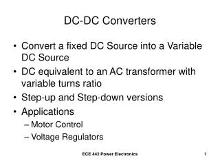
DC Choppers. 1. Prof. T.K. Anantha Kumar, E&E Dept., MSRIT. Introduction. Chopper is a static device. A variable dc voltage is obtained from a constant dc voltage source. Also known as dc-to-dc converter. Widely used for motor control. Also used in regenerative braking.


DC Choppers
E N D
Presentation Transcript
DC Choppers 1 Prof. T.K. Anantha Kumar, E&E Dept., MSRIT
Introduction • Chopper is a static device. • A variable dc voltage is obtained from a constant dc voltage source. • Also known as dc-to-dc converter. • Widely used for motor control. • Also used in regenerative braking. • Thyristor converter offers greater efficiency, faster response, lower maintenance, smaller size and smooth control. 2 Prof. T.K. Anantha Kumar, E&E Dept., MSRIT
Choppers are of Two Types • Step-down choppers. • Step-up choppers. • In step down chopper output voltage is less than input voltage. • In step up chopper output voltage is more than input voltage. 3 Prof. T.K. Anantha Kumar, E&E Dept., MSRIT
Principle Of Step-down Chopper 4 Prof. T.K. Anantha Kumar, E&E Dept., MSRIT
A step-down chopper with resistive load. • The thyristor in the circuit acts as a switch. • When thyristor is ON, supply voltage appears across the load • When thyristor is OFF, the voltage across the load will be zero. 5 Prof. T.K. Anantha Kumar, E&E Dept., MSRIT
6 Prof. T.K. Anantha Kumar, E&E Dept., MSRIT
7 Prof. T.K. Anantha Kumar, E&E Dept., MSRIT
8 Prof. T.K. Anantha Kumar, E&E Dept., MSRIT
9 Prof. T.K. Anantha Kumar, E&E Dept., MSRIT
10 Prof. T.K. Anantha Kumar, E&E Dept., MSRIT
11 Prof. T.K. Anantha Kumar, E&E Dept., MSRIT
12 Prof. T.K. Anantha Kumar, E&E Dept., MSRIT
3.1 Basic DC to DC converters 3.1.1Buck converter SPDT switch changes dc component Switch output voltage waveform Duty cycle D: 0 ≤ D ≤ 1 complement D: D´ = 1 - D
Thought process in analyzing basic DC/DC converters 1) Basic operation principle (qualitative analysis) –How does current flows during different switching states –How is energy transferred during different switching states 2) Verification of small ripple approximation 3) Derivation of inductor voltage waveform during different switching states 4) Quantitative analysis according to inductor volt-second balance or capacitor charge balance
Inductor voltage and current subinterval 1: switch in position 1
3.1.2Boost converter • Boost converter example
Continuous- Conduction- Mode (CCM) and Discontinuous Conduction-Mode (DCM) of boost
Methods Of Control • The output dc voltage can be varied by the following methods. • Pulse width modulation control or constant frequency operation. • Variable frequency control. 35 Prof. T.K. Anantha Kumar, E&E Dept., MSRIT
Pulse Width Modulation • tON is varied keeping chopping frequency ‘f’ & chopping period ‘T’ constant. • Output voltage is varied by varying the ON time tON 36 Prof. T.K. Anantha Kumar, E&E Dept., MSRIT
37 Prof. T.K. Anantha Kumar, E&E Dept., MSRIT
Variable Frequency Control • Chopping frequency ‘f’ is varied keeping either tONor tOFF constant. • To obtain full output voltage range, frequency has to be varied over a wide range. • This method produces harmonics in the output and for large tOFFload current may become discontinuous 38 Prof. T.K. Anantha Kumar, E&E Dept., MSRIT
39 Prof. T.K. Anantha Kumar, E&E Dept., MSRIT
Step-down ChopperWith R-L Load 40 Prof. T.K. Anantha Kumar, E&E Dept., MSRIT
When chopper is ON, supply is connected across load. • Current flows from supply to load. • When chopper is OFF, load current continues to flow in the same direction through FWD due to energy stored in inductor ‘L’. 41 Prof. T.K. Anantha Kumar, E&E Dept., MSRIT
Load current can be continuous or discontinuous depending on the values of ‘L’ and duty cycle ‘d’ • For a continuous current operation, load current varies between two limits Imaxand Imin • When current becomes equal to Imaxthe chopper is turned-off and it is turned-on when current reduces to Imin. 42 Prof. T.K. Anantha Kumar, E&E Dept., MSRIT
43 Prof. T.K. Anantha Kumar, E&E Dept., MSRIT
Expressions For Load CurrentiO For Continuous Current Operation When Chopper Is ON (0 t tON) 44 Prof. T.K. Anantha Kumar, E&E Dept., MSRIT
45 Prof. T.K. Anantha Kumar, E&E Dept., MSRIT
46 Prof. T.K. Anantha Kumar, E&E Dept., MSRIT
47 Prof. T.K. Anantha Kumar, E&E Dept., MSRIT
When Chopper is OFF 48 Prof. T.K. Anantha Kumar, E&E Dept., MSRIT
49 Prof. T.K. Anantha Kumar, E&E Dept., MSRIT
50 Prof. T.K. Anantha Kumar, E&E Dept., MSRIT