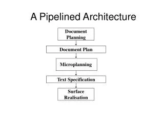
Pipelined Architecture
Microprocessor Architecture. UOP S.E.Comp (Sem-I). Pipelined Architecture. Prof.P.C.Patil Department of Computer Engg Matoshri College of Engg.Nasik pcpatil18@gmail.com. Bus Cycles of 80386. Bus Cycles of 80386.


Pipelined Architecture
E N D
Presentation Transcript
Microprocessor Architecture UOP S.E.Comp (Sem-I) • Pipelined Architecture Prof.P.C.Patil Department of Computer Engg Matoshri College of Engg.Nasik pcpatil18@gmail.com.
Bus Cycles of 80386 • The internal and external bus operations of 80386 are synchronized by the clock signal. • The 80386 perform variety of machine (bus) cycles in response to intemal requirements and external requirements • There are seven types of machine (bus) cycles • In each machine cycles corresponding status signals are activated. • The memory read and memory write machine cycles can be locked to prevent another bus master from using the bus.
Bus Cycles of 80386 • In each machine cycles corresponding status signals are activated. • The memory read and memory write machine cycles can be locked to prevent another bus master from using the bus.
Bus Cycles of 80386 • Seven types of machine (bus) cycles/operations. 1) Memory read 2) Memory write 3) I/O read 4) I/O write 5) Lestruction fetch 6) Interrupt acknowledge 7) Halt/Shut down
System Clock • System clock syrchronizes the internal and external bus operations in the 80386DX. • The 80386DX can operate on four different clock speeds • 80386DX - 16 (16 MHz) • 80386DX - 20 (20 MHz) • 80386DX - 25 (2s MHz) • 80386DX- 33 (33 MHz) • Operating frequency of the 80386DX is half of, the CLK2 frequency. • Therefore, CLK2 of an 80386DX - 20 is driven by 40 MHz signal. (Shown in Fig below)
Bus States • Each machine (bus) cycle consists of at least two bus states T1 and T2, • and each bus state consists of two CLK cycles. • During the first bus state (T1), address and bus status pin are active. • During the second bus state (T2), actual data lransfer takes place. • The 80386 DX can perform two types of machine cycles : • Nonpipelined • Pipelined.
Dynamic Bus Sizing • Dynamic data bus sizing is a feature allowing direct processor connection to 32-bit or 16-bit data buses for memory or I/O. • A single processor may connect to both size buses • Transfers to or from 32 to 16 bit ports are supported by dynamically determining the bus width during each machine cycle. • The 80386DX microprocessor's bus size 16 (BS-16 [Bar/Complement]) )input is used to inform the 803B6DX at the currently addressed device is a 16-bit device rather than a 32-bit device‘
Nonpipelined Bus Cycle • During T1, the 803B6DX sends the address, bus status signal and control signals. • In case of write cycle, data to be output is also send on the data bus, during T1. • After address access time, read or write data transfer takes place over the data bus. • This activity is carried out in T2.
Pipelined Machine (Bus) Cycles
Pipelined Bus Cycle • Pipelining allows machine cycles to be overlapped. • The main advantage of pipelining is that it increases the amount of time required for the memory or I/O device to respond. • This time is also referred as access time. • The 80386DX implements pipelining by overlapping addressing of the next bus cycle with the data transfer of previous bus cycle.
Pipelined Bus Cycle • Fig shows that address becomes valid in T2 state of the previous bus cycle, and the data transfer for address takes place in T2-state of the current bus cycle. • IMP : address An + 1 becomes valid during T2 of the current bus cycle and actual data transfer for address An + 1 takes place in T2 state of the next bus cycle. • If the processor is 80386DX-20 then one T-state time is 50 ns. • In pipelined bus cycle the access time for memory and I/O device is 100 ns whereas access time for memory and l/O device in nonpipelined bus cycle is approximately 50 ns.
Nonpipelined Read Cycle
Nonpipelined Read Cycle The sequence of events for the nonpipelined read cycle: • The read operation starts at the beginning of phase in the T1 state of the bus cycle. • In this phase, 80386DX sends the address on the address busand enables signals(BE0 (Bar) - BE3 (Bar)) according to data transfer type. • In the same phase, it activates ADS (Bar)signal to indicate valid address is placed on the address bus. • In phase 1 of T1 - state it also activates the bus cycle definition signals : M/IO, D/C and W/R.
Nonpipelined Read Cycle • At the beginning of phase 1 of T2 state, extemal device activates BS16 (BAR)signal. • Then samples this signal in the middle of phase 1 of T2-state. • 32-bit data transfer: If BS16 (BAR) =1 • 16-bit data transfer: If BS16 (BAR) =0 • The 80386 DX does this data transfer in phase 2 of T2-state. • At the end of phase 2 of T2-state the READY (BAR) signal is sampled. • The logic 1 on this signal inserts wait state in the current bus cycle to extend the bus cycle.
Nonpipelined Read Cycle • The LOCK (Bar)signal low indicates that it is bus locked cycle. • If bus cycles are locked the other bus master is not allowed to take control of the bus between two locked bus cycles.
Nonpipelined Write Cycle
Nonpipelined Write Cycle The sequence of events for the nonpipelined read cycle: • It is similar to nonpipelined read cycle. • The write operation starts at the beginning of phase 1 in the T1 state of the bus cycle. • In this phase, 80386DX sends the address on the address bus and enables signals BE0(Bar) -BE3(Bar) according to data transfer type. • After sending address in the same phase it activates its ADS(Bar) signal to indicate valid address is placed on the address bus.
Nonpipelined Write Cycle • In phase 1 of T1-state it also activates the bus cycle definition signals M/IO, D/C and W/R • At the beginning of phase 2 of T1-state, it sends data on the data bus. This data remains valid until the start of phase 2 of the T1-state of the next bus cycle. • At the end of phase 2 of T1- state, ADS(Bar)is returned to its inactive logic 1 states. • The address bus, byte enable pins, and bus status pins remain active through the end of the write cycle.
Nonpipelined Write Cycle • In the middle of phase 1 of T2-State, 80386DX samples BS16(Bar) input. • If this signal is high, 80386 DX does the 32-bit data transfer otherwise 80386DX performs 16-bit data transfer. Comparison of Read and Write Cycle
Pipelined Read/Write Cycle
Pipelined Read/Write Cycle • In the pipelined bus cycle the address for the next bus cycle is sent during the T2 - state of the current cycle. • NA (next address) signal initiates address pipelining.
Pipelined Read/Write Cycle • It then samples NA signal at the beginning of phase 2 of any T state in which ADS is not active, specifically. • In the second T-state of a non-pipelined address cycle • In the first T-state of a pipelined address cycle • In any wait state of a non-pipelined address or pipelined address cycle unless NA has already been sampled active
Pipelined Read/Write Cycle • The NA(Bar) is tested as 0 (active) during T2 of cycle 2 which ensures that 80386DX has to execute next cycle as pipelined bus cycle. • The cycle 2 (nonpipelined read cycle) is also extended with one wait state because READY pin is not active, • in wait state, the valid address for the next bus cycle is sent on the address bus as next bus cycle is pipelined bus cycle.
Pipelined Read/Write Cycle • The next cycle (cycle 3) is pipelined write cycle. • In this, data is sent on the data bus in phase 2 of T1p-state and remains valid for the rest of the cycle. • The READY signal is sampled at the end of T2p - state. • As it is low, write cycle is completed without wait state.
Pipelined Read/Write Cycle • The next cycle (cycle 4) is pipelined read cycle. • In this, READY signal is tested 0 at the end of phase 2 of T2p - state. • This means that read cycle is completed without wait state. • It is important to note that due to pipelined address cycle, access time is extended and one state (T-wait) of read cycle is saved.