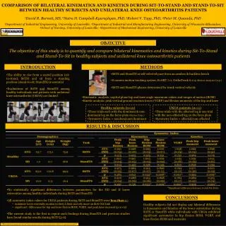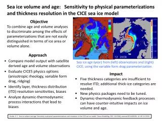
Rugged and Easily Maintained Steering System for Light Duty Trucks
This research aims to provide directional control for light duty trucks without specific specifications set by IAT. The study explores different components, types of connections, steering mechanisms, and setups to determine the desired qualities of the system. The research concludes that recirculating ball steering is the most suitable and cost-effective mechanism. The study also addresses the challenges in the original system setup and proposes a new setup for independent front suspension. The finalization of the geometry and Ackermann steering design will ensure optimal performance.

Rugged and Easily Maintained Steering System for Light Duty Trucks
E N D
Presentation Transcript
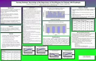
Objective • Provide directional control. • No specific specifications set by IAT. • Must be rugged and easily maintained.
Start • Research • Different components • Types of connections • Types of steering mechanisms • Types of set ups • Desired qualities of system
Conclusions of Research • Setup is based on mechanism. • Our purposes dictate only moderate responsiveness. • Ease of operation through gear ratio of mechanism.
Conclusions of Research Contd.. • Decided on recirculating ball steering. • Used in many older light duty trucks. • Balls act as a type of lubricant . • Among the least expensive that would satisfy our purpose. • Balls also keep play at the steering wheel tighter than other mechanisms which helps in responsiveness.
Contd… • Can mount any distance from the rotating axis of the steering knuckles. • Helps with calculations as I can vary the distance for best Ackermann steering results.
Problems • System was designed for solid front axle. • Very limited geometry.
New system setup • Allowed for more flexible geometrical setup to help work around other components. • Designed for independent front suspension • Symmetrical for part selection.
Steering knuckles • Component that works not only with the steering system but also the braking and suspension systems. • Must calculate the angle between steering arm and hub assembly as a start for finalizing geometry of entire system.
Hub Assembly • Θ = 38.66 Degrees
Specific Steering Mechanism • Siganaw 525 • Found on most 1980-1992 light duty trucks • Selection allows the calculation of the range of travel for the center linkage
Finalizing Geometry • Lengths of tie rods and center linkage depend on distance from mechanism to steering arm which is governed by wheel base and the suspension. • Must have more finalized suspension design to establish max distance to avoid unwanted tension and compression of components
Ackermann Steering Design • Ackermann steering helps deal with the fact that for turning stability the inside tire must turn at a larger angle
Ackermann Steering • Helps calculate the difference in turning angles by projecting a line perpendicular to each tire toward the rear axle and achieving the smallest distance between the lines. • Ideally they would meet at the same spot but the value will never be 0.00
After Proof • After proof the stated relationships exist and all relevant information is available I will calculate the turning angle λ by first calculating θ with the stated equations. • Once the two angles are established I will be able to establish the allowable center linkage travel for the calculated θ value and make sure that it is within what the mechanism can do.
Finalized Ackermann • By creating a drawing in AutoCAD in rectangular coordinates I can establish the slope of the lines the tires travel which will allow me to establish the equations of those lines. • Subsequently I can calculate the equations for the lines perpendicular that intersect a line drawn from the rear axle which represents the x- axis.
By setting the equations for the perpendicular lines to zero I can establish where they intersect the line from the rear axle. • Again the object is to achieve the smallest difference in x as possible based on the turn angles and distance of center linkage from the center line of hub assembly.
Now all information is available to calculate tie rod length to achieve the Ackermann steering and finalize the geometry to model and construct the steering system.