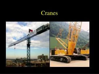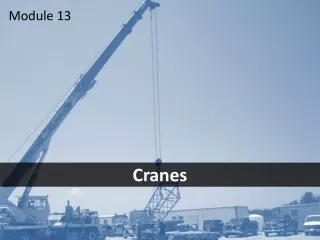
CRANES
TURBINE. CRANES. NEA39. PLANT STATUS!. General System Diagram of. Palo Verde Nuclear Generating Station. Legend::. Safety Injection Systems. Reactor Coolant System. To Switchyard. Containment Building. Main Steam System. Main Feedwater System. Main Condensate System.

CRANES
E N D
Presentation Transcript
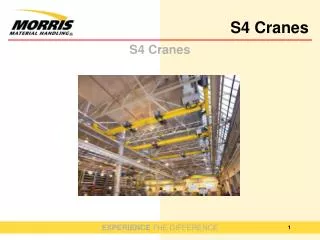
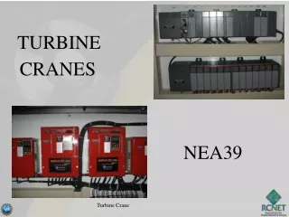
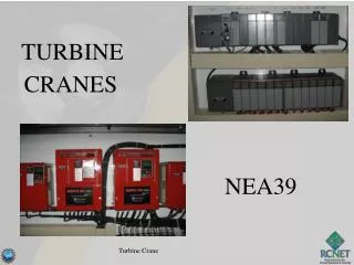
TURBINE CRANES NEA39 Turbine Crane
PLANT STATUS! General System Diagram of Palo Verde Nuclear Generating Station Legend:: Safety Injection Systems Reactor Coolant System To Switchyard Containment Building Main Steam System Main Feedwater System Main Condensate System CONTAINMENT SPRAY Circulating Water System Transformer Turbine Building Auxiliary Feedwater System Cooling Tower and Fans Safety Injection Tank Moisture Separator Reheaters MSSVs ADVs 8 8 8 Steam Generator Auxiliary Building MSIV Pressurizer MTSV Control Rods MSSS Shutdown Heat Exchanger HP LP LP LP Generator Bldg. Turbine Turbine Turbine Turbine Equipment Cooling MTCV Z From Auxiliary Feedwater Pumps Containment Spray Pump Turbine Bypass Valves Reactor Core Refueling Water Tank Condensate Pump Reactor Coolant Pump Main Condenser Low Pressure Safety Injection Pump (HP) Feedwater Heaters (LP) Feedwater Heaters Circulating Water Pump High Pressure Safety Injection Pump Feedwater Regulation Valve Main Feedwater Pump Polishing Demineralizers Containment Sump Turbine Crane PV Daily Status Report
Walk downs • Review instructions to ensure workable and adequate • Right Parts/materials/tools • Permits • Relevant Operating Experience Turbine Crane
Pre Job Briefs • Understand the Task • Critical Steps identified and OE used AND what actions are being taken in reference to these two areas • Two Minute Drills: • Hazards identified AND what are actions are you taking Turbine Crane
Procedure Use & Adherence • WO / procedure in hand & latest revision • Place keepers being used • Sign steps as you go • Follow & understand steps - STOP if can't or don't Turbine Crane
TURBINE CRANE • Terminal Objective Given references provided by the Instructor, the Plant Electrician will maintain Turbine Building Cranes as demonstrated by achieving a minimum of 80% on a written examination. Turbine Crane
. Multi Stud Tensioner
PRE-JOB BRIEF • Identify Critical Steps • Identify Error Precursors • Worst thing that can happen • Error prevention defenses to be used • Actions to assure proper configuration control Turbine Crane
TURBINE CRANE EO 1.5 Discuss the Design of the Allen Bradley SLC 5/04 Programmable Logic Controller
Basis The Turbine Cranes at PVNGS have been upgraded to a newer technology utilizing programmable electronic devices to control and operate the various equipment associated with overhead cranes. PLC’s (or Programmable Logic Controllers) are basically the centralized brain and nervous system of the crane. They are used to receive commands from an operator (and/or components) and quickly provide intelligent signals to various control and operating equipment (VFD’s etc…) on the crane. Turbine Crane
Basis • Utilize an SLC 500 operating platform with the SLC 5/04 version installed. • Utilize RSLogix 500 operating software Turbine Crane
Benefits • PLC’s offer a compact design • Modular and flexible system configuration • Communication speed • Precise and Smooth operation Turbine Crane
Component Hardware • The SLC 5/04 utilizes a modular style which includes: • Power Supply • Processor • Chassis • I/O modules & Flex I/O Turbine Crane
CPU Scanner Counter Modules Power Supply Turbine Crane
Flex I/O and associated equipment located in the cab enclosure Turbine Crane
Hardware Power Supply: • Provides system power requirements for the processor and the I/O modules. • Many models are available and are typically sized to the voltage and current requirements of the end user. • LED is lit when proper voltage is supplied • Not considered a chassis slot. Turbine Crane
Power Supply Turbine Crane
This LED is lit when the proper voltage is being supplied Turbine Crane
Hardware Processor: (or CPU) • Considered the Brain of the entire system which performs the following functions: • Receives information from the Input devices via and I/O module. • Makes decisions based on input received and program installed • Sends information the output devices via an I/O module. Turbine Crane
Hardware Chassis: • The Chassis is the hardware assembly which physically houses the Processor and I/O modules associated with the PLC. It also performs the following functions: • Provides power distribution from the power supply • Provides the communication path from the processor to/from the modules. Turbine Crane
Hardware Chassis: • Assigns a Software address used by the processor • Assigns a hardware address based on the slot number, module type etc. • Processor is always slot 0 • Input and Output (& I/O) modules will be in slot 1-? • Houses components in the following sizes: • 4-slot • 7-slot • 10-slot • 13-slot Turbine Crane
Hardware Chassis: • The Chassis’ can be ganged together using an interconnecting cable with a maximum of 3 total used. • Remote I/O can also be utilized and is used on the Turbine Crane. Turbine Crane
What type of Chassis do we use????? Interconnecting Cable (1746-C9) Turbine Crane
Hardware I/O Modules: • I/O modules are electronic units which are designed to provide the interface between the cranes input and output devices (Processor, Joysticks, Drives, Encoders etc…). These modules can be Input, Output or I/O (Combination). Turbine Crane
Hardware I/O Modules: • Designed to plug into the Chassis • Come in various forms that provide various functions. The most common are: • Analog – sends or receives infinitely variable signals. • Input signal examples include Potentiometers, Joysticks • Output signal examples include VFD’s, recorders, actuators, valves and meters. • Digital (Discreet) – sends or receives on/off (1 or 0) signals • Input signal examples include circuit breakers, limit switchs, contactors and pushbuttons. • Output signal examples include alarms, lights solenoids. • Process Control – used for varying control of signals Turbine Crane
Basic Signal Operation: Data/Operational Flowpath: • A signal would be derived from an input device such as a pushbutton, joystick, encoder etc… and it would then be sensed/delivered to the input module. • The input module will take the signal and convert it to the necessary language (Data File type) supported by the processor and deliver the signal with an address to the processor. Turbine Crane
Basic Signal Operation: Data/Operational Flowpath: • Data file types include: • Output • Input • Status • Binary • Timer • Counter • Control • Integer • Floating Point • ASCII • String Turbine Crane
Basic Signal Operation: Data/Operational Flowpath: • The Processor will read what the input module sent, interpret the data and compare it with the program files (ladder logic). It will then make the necessary decisions and provide an output in the correct format to the output module • The Output Module will interpret the information sent from processor and provide an output signal to the prescribed output device (Drive, relay, lamp, etc…) Turbine Crane
Basic Signal Operation: Communications Equipment: • Network - A series of stations (or nodes) which are physically connected together. • Node – A device on a network which is capable of sending or receiving information. • Link – The physical means of sharing or transmitting data between 2 or more locations. • Baud – Measurement of signal speed typically across a communications link (usually in bits per second) Turbine Crane
Basic Signal Operation: Connections & Networks: • Data Highway plus (DH+) – Local area network that is designed to support remote programming. • Fairly high speed • Up to 230 kbits/sec based on distance of cable. • Can have up to 64 nodes • Cable lengths to 10,000 ft. • Computer connection requires a PCMK link and RSLinx software. Turbine Crane
Basic Signal Operation: Connections & Networks: • RS-232 Connection (Serial) • Medium speed • Up to 19kbits/sec • Requires a 1747-CP3 cable and RSLinx software Turbine Crane
Basic Signal Operation: Connections & Networks: • Universal Remote I/O Netowrk – Used to connect SLC 500 processors to remote I/O chassis and other intelligent devices. • Fairly high speed • Up to 230 kbits/sec • Can have up to 16 nodes • Uses a 1747-SN (Scanner Module) and an Adapter Module - ASB Turbine Crane