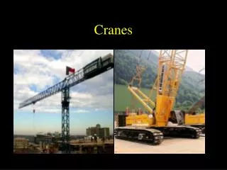
CRANES
Daily status report for Turbine Crane operations at Palo Verde Nuclear Generating Station. Includes walk-downs, procedures, briefs, and maintenance tasks.

CRANES
E N D
Presentation Transcript
TURBINE CRANES NEA39 Turbine Crane
PLANT STATUS! General System Diagram of Palo Verde Nuclear Generating Station Legend:: Safety Injection Systems Reactor Coolant System To Switchyard Containment Building Main Steam System Main Feedwater System Main Condensate System CONTAINMENT SPRAY Circulating Water System Transformer Turbine Building Auxiliary Feedwater System Cooling Tower and Fans Safety Injection Tank Moisture Separator Reheaters MSSVs ADVs 8 8 8 Steam Generator Auxiliary Building MSIV Pressurizer MTSV Control Rods MSSS Shutdown Heat Exchanger HP LP LP LP Generator Bldg. Turbine Turbine Turbine Turbine Equipment Cooling MTCV Z From Auxiliary Feedwater Pumps Containment Spray Pump Turbine Bypass Valves Reactor Core Refueling Water Tank Condensate Pump Reactor Coolant Pump Main Condenser Low Pressure Safety Injection Pump (HP) Feedwater Heaters (LP) Feedwater Heaters Circulating Water Pump High Pressure Safety Injection Pump Feedwater Regulation Valve Main Feedwater Pump Polishing Demineralizers Containment Sump Turbine Crane PV Daily Status Report
Walk downs • Review instructions to ensure workable and adequate • Right Parts/materials/tools • Permits • Relevant Operating Experience Turbine Crane
Pre Job Briefs • Understand the Task • Critical Steps identified and OE used AND what actions are being taken in reference to these two areas • Two Minute Drills: • Hazards identified AND what are actions are you taking Turbine Crane
Procedure Use & Adherence • WO / procedure in hand & latest revision • Place keepers being used • Sign steps as you go • Follow & understand steps - STOP if can't or don't Turbine Crane
TURBINE CRANE • Terminal Objective Given references provided by the Instructor, the Plant Electrician will maintain Turbine Building Cranes as demonstrated by achieving a minimum of 80% on a written examination. Turbine Crane
. Multi Stud Tensioner
PRE-JOB BRIEF • Identify Critical Steps • Identify Error Precursors • Worst thing that can happen • Error prevention defenses to be used • Actions to assure proper configuration control Turbine Crane
TURBINE CRANE EO 1.7 Describe the Operation of the Turbine Building Crane
Basic Startup and Operation • Verify power is available from (X)E-NGN-L15D2 through a disconnect switch (X)EE-NGL-NGN-W01 • This disconnect is located in the Turbine Building 176’, plant north near the Generator End. Turbine Crane
Basic Startup and Operation • The Crane Operator would operate the Walkway Mainline Disconnect Switch and then CB104 (250A Breaker – Right Side Panel), the 40A Lighting Transformer Circuit Breaker and the Lighting Contactor Circuit Breaker. Turbine Crane
CB 104 Turbine Crane
Basic Startup and Operation • For Chair Operational Control: • CB113, CB604 and CB627 must be closed to energize the master control relay CR604 and the mainline relay CNT627 after the reset pushbutton is depressed. • All Variable Frequency Drives will now be energized and await commands from their Energized PLC’s. • With the remaining control breakers in the closed position, the operators chair should now be fully functional. Turbine Crane
Main Line Contacts Motor Resistors Trolley Motor Trolley Tach Trolley Brake Follow the Numbers Turbine Crane
CNT 627 Turbine Crane
Operational / Design Example • Main Hoist Control: • When the operator selects and operates the Main Hoist Lower Joystick the following logic occurs: (172) • 115Vac Power is supplied to the MHL Joystick contacts (JS3016) via the Main Crane Enclosure Power. • The joystick output (Discreet) signal is applied to the Flex I/O input module PLC2904 (171) • This signal is now assigned an address (I:1.1/00) and it is delivered to the Remote I/O Adapter module (188) Turbine Crane
Main Hoist Joystick Turbine Crane
Main Hoist Joystick Turbine Crane
115Vac 12Vdc Turbine Crane
115Vac Turbine Crane
DiscreteInput Signal 12Vdc Analog Signal Assigned Address I:1.1/00 Assigned Address I:1.2/00 Turbine Crane
Remote I/O Adapter Module In the Operators Cab Turbine Crane
Operational / Design Example • Main Hoist Control: • When the operator selects and operates the Main Hoist Lower Joystick the following logic occurs: • The Remote I/O Adapter module communicates with the Scanner module and the signal is supplied directly to the CPU. • The CPU reads the signal and makes the decision and sends a corresponding signal to a Relay Output Module (PLC 2445). • This signal is now sent to the Magnetek VFD (AFD 228 Term S2) Turbine Crane
CPU SCANNER PLC OUTPUT MODULE PLC2445 Turbine Crane
Discrete Signal sent to S2 Turbine Crane
Operational / Design Example • Main Hoist Control: • When the operator selects and operates the Main Hoist Lower Joystick the following logic occurs: • 12Vdc Power in supplied to the MHL Joystick Potentiometer (JS3016) via 12Vdc PWR3005 • The joystick output (Analog) signal is applied to the Flex I/O Analog Input module PLC 2944 • This signal is now assigned an address (I:1.2/00) and it is delivered to the Remote I/O Adapter module Turbine Crane
Analog Output 0-12Vdc Turbine Crane
DiscreteInput Signal 12Vdc Analog Signal Assigned Address I:1.1/00 Assigned Address I:1.2/00 Turbine Crane
Remote I/O Adapter Module In the Operators Cab Turbine Crane
Operational / Design Example • Main Hoist Control: • When the operator selects and operates the Main Hoist Lower Joystick the following logic occurs: • The Remote I/O Adapter module communicates with the Scanner module and the signal is supplied directly to the CPU. • The CPU reads the signal and makes the decision and sends a corresponding signal to a Relay Output Module (PLC 1905). • This 4-20Ma signal is now sent to the Magnetek VFD (AFD 228 Term A2) Turbine Crane
Analog (4-20Ma) Signal sent to A2 Turbine Crane
Operational / Design Example MAIN HOIST Auxiliaries Control: • When the operator selects and operates the Main Hoist Lower Joystick the following logic occurs (continued): • 115Vac Power is supplied to the MHL Lower Limit Switch (LS2154) via CB702 • The limit switch position will determine the ability of the crane to further lower. • This signal is sent to PLC 2146 is now assigned an address (I:1504) and it is routed to the CPU Turbine Crane
Geared Limit Switches Assigned Software Address Turbine Crane
PLC2146 Input Module Turbine Crane
Operational / Design Example MAIN HOIST Brake Control: • When the operator selects and operates the Main Hoist Lower Joystick the following logic occurs (continued): • 115Vac Power is supplied to the VFD (AFD228) • When the joystick is selected for lower, the AFD discreet input S2 receives a signal as described above. • This signal is now operates a set of contacts (M0-M1 & M2-M3) which in turn actuate Relays CNT1003 and CNT1005 • The Brakes will now release as directed by the VFD and the hoist may be operated. Turbine Crane
Brake Contacts Turbine Crane
Operational / Design Example MAIN HOIST Encoder: • When the operator selects and operates the Main Hoist Lower Joystick the following logic occurs (continued): • Two Main Hoist Encoders will now begin to provide an output. • Encoder “A” (Motor Encoder) will provide input directly to the VFD (AFD228). • The VFD will in turn provide an output signal to PLC 1306 • The signal is now assigned a software address (I:0300) and it is routed to the CPU • The Main Hoist Drum Encoder will also read hoist motion and provide this signal to PLC 1306. • The signal is now assigned a software address (I:0301) and it is routed to the CPU Turbine Crane
Operational / Design Remaining Equipment: • The Aux Hoist, Trolley, Bridge, Service Hoist and Trolley will all function in a similar manner to the Main Hoist. Turbine Crane