Download
1 / 1
10 likes | 152 Vues
Observation and Numerical Calculation of Lorentz Detuning for the Cryomodule Test of STF Baseline Cavities at KEK-STF. TU5PFP075. Y. Yamamoto , H. Hayano, E. Kako, T. Matsumoto, S. Michizono, T. Miura, S. Noguchi, M. Satoh, T. Shishido, K. Watanabe(KEK) and T.X. Zhao(TIPC). abstract

E N D
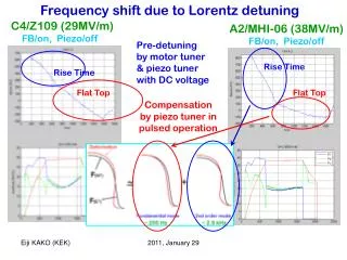
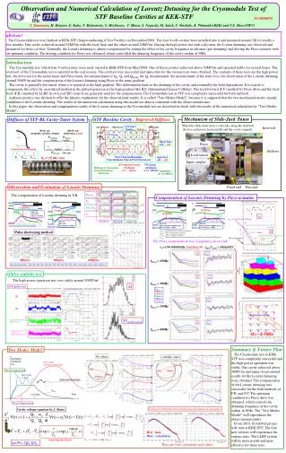
Observation and Numerical Calculation of Lorentz Detuning for the Cryomodule Test of STF Baseline Cavities at KEK-STF TU5PFP075 Y. Yamamoto, H. Hayano, E. Kako, T. Matsumoto, S. Michizono, T. Miura, S. Noguchi, M. Satoh, T. Shishido, K. Watanabe(KEK) and T.X. Zhao(TIPC) abstract The Cryomodule test was finished at KEK-STF (Superconducting rf Test Facility) on December/2008. The four 9-cell cavities were installed into it and measured around 2K for totally a few months. One cavity achieved around 32MV/m with the feed-back and the others around 20MV/m. During the high power test with a klystron, the Lorenz detuning was observed and measured for these cavities. Generally, the Lorentz detuning is almost compensated by setting the offset of the cavity frequency in advance (pre-detuning) and driving the Piezo actuator with an optimum condition. The driving condition for Piezo was obtained, which controlled the detuning frequency of the cavity within ±30Hz. Introduction The Cryomodule test, which four 9-cell cavities were used, started at KEK-STF from May/2008. One of these cavities achieved above 30MV/m and operated stably for several hours. The overview of the Cryomodule test is reported in the oral session. The cold test was successful and many data for the various tests were obtained. The contents of these tests are the high power test, the drive test for the motor tuner and Piezo tuner, the measurement of QL, Qt and QHOM, the Q0 measurement, the measurement of the static loss, the observation of the Lorentz detuning around 30MV/m and the compensation of the Lorentz detuning using Piezo at the same gradient. The cavity is generally deformed, when it is operated at the high gradient. This deformation leads to the detuning of the cavity and eventually the field degradation. It is crucial to compensate this effect by an artificial method in the pulsed operation at the high gradient like ILC (International Linear Collider). The feed-forward (F.F.) method by Piezo drive and the feed-back (F.B.) method by LLRF (Low Level RF) control are generally used for the compensation. The Cryomodule test at STF was completely successful for both methods. A physics picture was devised to offer the physics explanation for the observational results. It is called “Two Modes Model”, because it is supposed that the two mechanical modes mainly contribute to the Lorentz detuning. The results of the numerical calculation using this model are almost consistent with the observational ones. In this paper, the observation and compensation results of the Lorentz detuning in the Cryomodule test are described in detail with the results of the numerical calculation by “Two Modes Model”. Mechanism of Slide-Jack Tuner Stiffness of STF-BL Cavity-Tuner System STF Baseline Cavity ;Improved Stiffness When the Slide-Jack moves vertically along the stud bolt, the free end moves horizontally and the cavity expands. Cell Taper 13 deg. →10 deg. Invar rod 95 N / mm (endplate, cylinder, flange) 290 N / mm (slide-jack, piezo) TTF Cavity KJacket KTuner Fr Magnetic shield Beam Tube f78 → f84 Piezo Fz FZ FZ STF Baseline Cavity Lorentz Force Detuning Bellows KCavity 3 N / mm Load sensor Thick Titanium Baseplate, Thick Nb Beam Tube & Thick Nb End-cell Input Port f40 → f60 KS = 72 kN / mm Input coupler STF Baseline Cavity TTF Cavity Stiffness of Cavity Sys.72 kN/mm22 kN/mm Lorentz DetuningD f=- 150 HzD f =- 500 Hz at flat-top Estimation at 31.5 MV/m Observation and Evaluation of Lorentz Detuning Fixed end Free end The compensation of Lorentz detuning by F.B. PKlystron Compensation of Lorentz Detuning by Piezo actuator Eacc Pin QL Pin Pin Pin Log10 Eacc 32.6MV/m f in f in f t 30.5MV/m 32.0MV/m Δf F.B. Off Piezo Off No pre-detuning f t 30.5MV/m φ f t VPiezo QL VPiezo Pt ~ Eacc foffset from linear fitting Pt ~ Eacc Pt ~ Eacc Pt ~ Eacc full pulse flat top pulse end F.B. ON Piezo Off Pre-detuning (~300Hz) F.B. Off Piezo ON(500V/300Hz/0.8msec) Pre-detuning (~300Hz) F.B. Off Piezo ON(500V/350Hz/0.2msec) Pre-detuning (~360Hz) f t foffset : Initial offset of cavity frequency fPiezo : Drive frequency of Piezo VPiezo : Drive voltage of Piezo tdelay : Time difference between starting time of Piezo action and RF pulse Pulse shortening method Δf Δf distribution during the flat-top On resonance The Piezo compensation was completely successful! fSG=1300.500000MHz, Feed Back Off foffset/Vpiezo = 300Hz/500V 400μsec 800μsec 1480μsec fPiezo = 250Hz measurement points : 100, 200, 300, 400, 450, 500, 550, 600, 700, 800, 900, 1000, 1100, 1200, 1300, 1400, 1480μsec Pulse stability test The high power operation was very stable around 30MV/m! fPiezo = 300Hz Δf 2000 pulses data tdelay 0.2msec 0.4msec 0.6msec 0.8msec 1.0msec QL ~16 minutes fPiezo = 350Hz Δf r.m.s. : 5.4Hz ΔVpeak-to-peak peak field at flat-top (ADC counts) fPiezo = 400Hz < 0.1% (average) peak-to-peak ratio at flat-top (field degradation) Δf<~±30Hz Summary & Future Plan The Cryomodule test at KEK-STF was completely successful and the high power operation was stable. One cavity achieved above 30MV/m and many observational results for the Lorentz detuning were obtained. The compensation of the Lorentz detuning was successful for the both methods of F.B. and F.F. The optimum condition for Piezo drive was obtained, which controls the detuning frequency of the cavity within ±30Hz. The “Two Modes Model” well reproduces the observational results. From 2010, S1-Global project will start at KEK-STF. The four new cavities will experience the various tests. The LLRF system will be more useful and more effective for these tests. Two Modes Model No offset +400Hz offset Oscillation Amplitude (Xk) Slow mode (several hundred Hz) 500μsec 0μsec Offset Compensation 0μsec 1500μsec Fast mode (~kHz) 500μsec 1500μsec Stationary Amplitude Eacc Time 1.5 msec. Piezo Compensation Comparison between observational data and numerical calculation Cavity voltage equation by J. Slater Red : data Blue : calculation Equi-angular Spiral tanΨ=-2QLΔf/f0 They are very consistent each other!