3- Pipsqueak Piston and Cylinder
360 likes | 622 Vues
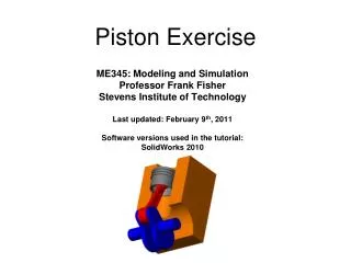
3- Pipsqueak Piston and Cylinder. Work holding in the Lathe.

3- Pipsqueak Piston and Cylinder
E N D
Presentation Transcript
Work holding in the Lathe • Collets have definite advantages over chucks in gripping work pieces in the lathe. They apply even gripping force to almost the entire diameter of the work piece. Collets are a more accurate means of work holding than chucks. They don’t distort thinner walled parts and don’t leave chuck jaw marks. They are however limited in size and part geometry.
Manufacturing a Pipsqueak Piston By gripping on one feature of a part while machining another, it is possible to machine a part without extra stock for chucking.
Facing piston stock Face piston stock to finish length. Standard pipsqueak piston stock is ½” cold rolled 1018 steel.
Form tool setup Piston rod-end being shaped with a form tool. Piston has been faced to finish length prior to this operation.
High speed steel tool cutting speeds Select surface feet per minute speed for cutting low carbon steel.
Cutting speeds are established to give maximum productivity without compromising tool life. Cutting speed charts generally give speeds that can be used in ideal conditions. Ideal conditions would include essential cooling and lubrication of the cutting tool, adequate machine horsepower and rigidity, sharp rigid quality cutting tools and adequate means of rigidly holding the work piece. Adjusting the cutting parameters such as speed, feed and depth of cut to compensate for the lack of ideal conditions is often necessary. Using lower cutting speeds generally do not adversely affect part quality. Due to lack of ideal conditions (cooling and lubricating elements), reduce RPM and feed by approximately. 50%
RPM selection Select RPM for ½” diameter and recommended surface feet per minute.
Form tool cutting Stock is extended a minimum amount for rigidity. Use correct speed and cutting fluid for high speed steel tool.
Cut remainder of ¼” radius Tool is positioned to back side of work piece and machine is run in reverse.
Piston stock is held in collet block in mill vise Use correct feed and speed. Subtract finish thickness from starting thickness. Remove half of extra stock from this side.
Measure carefully as you proceed. Using micrometers to measure piston rod-end
Collet block has been rotated 180 degrees and second side has been finished. Rotated collet block
Now would also be a good time to chamfer this hole to give clearance for the radius on the piston rod-end bushing flange. Ream hole
Radius tool setup Chuck piston back in lathe and cut next radius with form tool. Note that part is extended a minimum amount for rigidity. Use correct speed and cutting fluid.
Extend part about 1/3 of rod length and turn to finish diameter. Turning down piston rod
Extend part so that last 2/3 can be turned to size then turn second, then third section to finish size. Turning down rod
Optional radius under piston head. Leave a shoulder for form tool to cut final radius. Radius tool setup
Piston rod is cut to size. Finish with emery cloth if desired. Finished piston rod
Deburr rod-end hole and chamfer for bushing radius if you haven’t previously done it. Deburring rod-end hole
Cut stock 1/16” longer than finished part.Face cylinder to length in lathe.Make decorative cuts and end radius if desired.Drill and ream cylinder bore.Drill and tap pivot shaft connection.Drill air hole. Pipsqueak Cylinder
Reaming cylinder bore Avoid aggressive drilling when working with brass or acrylic plastic. These two materials have a tendency to pull drills into the work. This can cause cracking in the acrylic and broken drills or drill shanks spinning in the drill chuck when drilling brass. Drill geometry can be modified to avoid this problem.
When creating intersecting holes in a part, consider the fact that when a drill encounters a hole or void in its path, it will follow the path of least resistance and can deviate from a straight path. Do your drilling and reaming operations in an order where this will not be a factor. (Drill and ream the cylinder bore before drilling the air hole or the pivot shaft hole.)
After finishing cylinder bore, support ¾” hex brass cylinder in vise with parallels so that top hex face is flat. Cylinder setup
Face the top cylinder flat just to barely clean up. Remove a minimum amount of material. Facing cylinder side
Edge find the cylinder end. Also edge find the two vise jaws and split the difference to find centerline of the cylinder. Drill and tap the hole that the pivot shaft will thread into. Use the same thread size the shaft ends were tapped with. Don’t forget to drill the air hole. Machining cylinder side holes