Download

1 / 47
470 likes | 662 Vues
Compensation The process of correcting for flourescence crosstalk. History of compensation by traditional flow cytometry Compensating Image Stream Data Troubleshooting compensation in IDEAS. Why is compensation necessary?. Broad emmision spectra

E N D
CompensationThe process of correcting for flourescence crosstalk
History of compensation by traditional flow cytometry • Compensating Image Stream Data • Troubleshooting compensation in IDEAS AMNIS CORPORATION-Compensation
Why is compensation necessary? • Broad emmision spectra • Imperfections in fluorescence filtering cause leakage into other channels • Tandem conjugates AMNIS CORPORATION-Compensation
The electromagnetic spectrum AMNIS CORPORATION-Compensation
Resonance Energy Transfer Resonance energy transfer is distance dependent and occurs without radiant release from the donor molecule AMNIS CORPORATION-Compensation
Spectral overlap AMNIS CORPORATION-Compensation
Band Pass Filters Filters with transmission that is high for a particular band of frequencies, but that falls to low values above and/or below this band AMNIS CORPORATION-Compensation
Beam splitter • A beam splitter is an optical device that splits a beam of light in two. • A dichroic mirror is a type of beam splitter that is able to split light of different wavelengths. AMNIS CORPORATION-Compensation
Traditional flow cytometer flow cell BD FACSCalibur Optics AMNIS CORPORATION-Compensation
Ch1 470-500nm Ch2 400-470nm Ch3 500-560nm Ch4 560-595nm Ch5 595-660nm Ch6 660-730nm The ImageStream® System AMNIS CORPORATION-Compensation
Spectral Decomposition 6 Spectral Channels 488-505nm Scatter 560-595nm PE 400-470nm DAPI 595-660nm PI, 7-AAD 505-560nm FITC 660-730nm Cy5, DRAQ5 0.3 degree separation per channel Deep Blue Corrector Petzval Lens Sets Objective & Quartz Cuvette Spectral DecompositionStack Field Lens Post Mag Lens AMNIS CORPORATION-Compensation
Flourescence Microscopy • The fluorescent microscope utilizes filter cubes that narrow the wavelenth of excitation and emission designed specifically for each fluorochrome. • Fluorescence microscopes typically do not apply compensation because each color is taken with a different set of optimized filters. From SemRock AMNIS CORPORATION-Compensation
The crosstalk can be quantified and corrected Givans AMNIS CORPORATION-Compensation
Compensation of flow data during acquisition Figures from BD FACS Academy AMNIS CORPORATION-Compensation
Formula for traditional compensation xFn = the amount of signal in detector n that originates from fluorophore x Dn = the measured signal in detector n For each detector D=the sum of fluorescence from each fluorophore D1 = 1F1+ 2F1 +3F1 +…nF1 D2 = 1F2+ 2F2 +3F2 +…nF2 Dn = 1Fn+ 2Fn +3Fn +…nFn A matrix is defined such that each detector measured value is the sum of the peak fluorescence plus the spillover amount from every other fluorochrome. The matrix is used to remove the contribution of the non-peak fluorochrome. This gives you the ‘true’ value for the peak fluorochrome. AMNIS CORPORATION-Compensation
Factors affecting matrixes • Crosstalk is fluorochrome specific • Tandem conjugates can have dual band fluorescence due to the inefficiency of RET to the acceptor or degradation of the conjugate • Bright vs Dim fluorescence • Autofluorescence is cell specific AMNIS CORPORATION-Compensation
Compensation of dim to bright cells AMNIS CORPORATION-Compensation
BD Fluorescence Spectrum Viewer AMNIS CORPORATION-Compensation
BD Fluorescence Spectrum Viewer AMNIS CORPORATION-Compensation
BD Fluorescence Spectrum Viewer AMNIS CORPORATION-Compensation
Spectral Compensation Post-acquisition compensation is applied to images on a pixel by pixel basis in IDEAS. Single color control samples used to calculate a 6x6 matrix. SSC Brightfield FITC PE PE-Alexa610 Draq-5 AMNIS CORPORATION-Compensation
Compensating ImageStream data pixel by pixel • Corrections are applied before spectral compensation. • ASSIST values are used for: • 1.Darkcurrent correction • 2.Brightfield gain correction • 3.Spatial registration Brightfield compensation is done using the background around the objects and is automatically computed and applied when the data file is loaded in IDEAS. Single fluorochrome compensation control files are used for fluorescence crosstalk compensation. AMNIS CORPORATION-Compensation
1023 950 1000 475 425 500 500 475 425 800 725 775 700 625 675 725 800 775 1000 1023 950 500 475 425 800 775 725 625 675 700 500 475 425 1000 1023 950 Signal Signal Spectral Overlap Dark Current Correction Spectral Compensation Pixelated Imagery Read Out 1023 Signal 40 Spectral Overlap 35 25 Dark Current 0 Green Channel Orange Channel Red Channel AMNIS CORPORATION-Compensation
Darkcurrent correction • Each pixel on a CCD detector has a characteristic baseline output known as dark current offset. AMNIS CORPORATION-Compensation
Brightfield gain correction • Each pixel on a CCD detector has a characteristic responsivity to light exposure, known as the pixel gain. AMNIS CORPORATION-Compensation
Spatial registration • Spatial registration errors between image channels is measured by imaging the same object (SpeedBead) in all 6 channels simultaneously and comparing the location of the images. AMNIS CORPORATION-Compensation
IDEAS Tools • The corrections are available to the user in IDEAS during data analysis. AMNIS CORPORATION-Compensation
Spectral Compensation: Matrix Development Cross talk matrix is determined by calculating best fit linear regression for each dye into each channel. Slope of linear regression is matrix coefficient. A 6x6 martix of linear equations is solved for each pixel in every image to remove cross talked light. AMNIS CORPORATION-Compensation
Potential pitfalls to watch for • Saturation • Mis-alignment • Coefficients calculated on poorly fit lines • Autoflourescence • Camera staging AMNIS CORPORATION-Compensation
Misalignment AMNIS CORPORATION-Compensation
Saturation • Saturation occurs when the pixel can no longer quantify the available light. • The 10 bit detector provides 1024 bins and once 1023 is reached the pixel can no longer quantify the signal and compensation becomes impossible. • It is therefore critical that events with saturated pixels be eliminated • During data acquisition the laser power, camera sensitivity and cell classifiers are used to reduce saturation AMNIS CORPORATION-Compensation
Saturation AMNIS CORPORATION-Compensation
Undercompensation due to saturated pixels… AMNIS CORPORATION-Compensation
Inactive area 12 pixels wide by X6 Active Channel 96 pixels wide by 512 pixels tall X6 256 FWD Stage Selection Staging the camera • Charged Coupled Device AMNIS CORPORATION-Compensation
Properly compensated single color controls AMNIS CORPORATION-Compensation
Mis-compensated single color controls AMNIS CORPORATION-Compensation
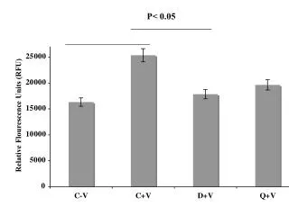
Compensation variation with laser power • Jurkat cells stained with NFkB FITC were run in the absence of brightfield and a 1000 images were collected with 488 laser excitation ranging from 20mw to 200mw at 20mw increments. Compensation values were calculated in IDEAS graphed over changing laser power. Compensation variation with increasing laser power shows little to no correlation to changing laser power. AMNIS CORPORATION-Compensation
20 mw positive 20 mw Blank 100 mw positive 100 mw Blank 200 mw positive 200 mw Blank Compensation variation with laser power AMNIS CORPORATION-Compensation
Two methods for calculating the matrix • The Means method is used for uniform objects like beads. • The Best Fit is used for objects that have a varied level of fluorescence. AMNIS CORPORATION-Compensation
Coefficient error • Check the matrix AMNIS CORPORATION-Compensation
IDEAS Compensation AMNIS CORPORATION-Compensation
Workflow • Collect files of single color fluorescent controls with brightfield turned off • Open IDEAS and start a New Matrix under compensation • Add the single color control files to the analysis (open and load files) • Select the single cells using the scatter area vs. aspect ratio dot plot to use as the compensation population • Assign the positive populations to the appropriate channels • Create the compensation matrix • Validate the matrix • Save the matrix • Use the matrix to open data files AMNIS CORPORATION-Compensation
Go forth and compensate! AMNIS CORPORATION-Compensation
Calculating the compensation matrix • Two channels of interest X and Y • Compute the variance of X (VarX), variance of Y (VarY) and the covariance of X and Y (CovXY). CovXY measures the degree to which 2 values vary together • Define a 2 x 2 matrix: • Eigen Value = • The major Eigen value is the positive value • Slope = Eigen values can be found for square symmetric matrices. There are as many eigen values as there rows (or columns) in the matrix. Conceptually they can be considered to measure the strength (relative length) of an axis (dervied from the square symmetric matrix). Each eigen value has an associated eigen vector. An eigen value is the length of an axis, the eigen vector determines its orientation in space. AMNIS CORPORATION-Compensation
1023 500 500 800 700 800 1023 500 800 700 500 1023 Pixelated Imagery Read Out 1023 Signal 40 Spectral Overlap 35 25 Dark Current 0 Green Channel Orange Channel Red Channel AMNIS CORPORATION-Compensation