Masonry Bracing
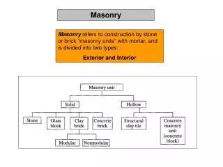
Masonry Bracing. Life Safety Considerations During Construction of Masonry Walls. FACTORS TO CONSIDER. Who is responsible for wall bracing? Engineer General Contractor Masonry Contractor Qualified Person. CODE REQUIREMENTS.

Masonry Bracing
E N D
Presentation Transcript
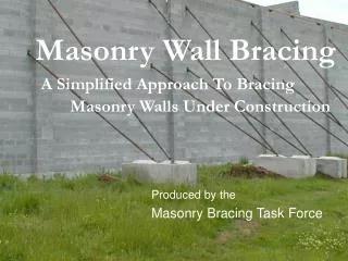
Masonry Bracing Life Safety Considerations During Construction of Masonry Walls
FACTORS TO CONSIDER Who is responsible for wall bracing? • Engineer • General Contractor • Masonry Contractor • Qualified Person
CODE REQUIREMENTS • 1926.706(b)All masonry walls greater than 8 feet in height must be braced to prevent overturning and collapse, • Unless adequately supported so it will not overturn or collapse • Bracing must remain in place until permanent supporting elements of the structure are in place
Code Requirements THEN WHAT? • Code does not give direction for spacing of braces • Vertical • Horizontal • Additional Height
Code Requirements LIMITED ACCESS ZONE (L.A.Z.) 1926.706(a) Some common misconceptions: • Limited Access Zones do not take the place of wall braces, • Wall braces do not take the place of L.A.Z, • Both are required
Test Wall Construction • 8 in. Lightweight Block • 2 - #4 Horizontal Rebar spaced 4 ft. on center • #5 Vertical Rebar spaced 4 ft. on center • Coil Loop Inserts with ¾” coil bolts • 2000 psi grout at rebar locations • Grouting in pours of 8ft.
Test Wall Construction Wall Brace connection • Coil Loop Inserts installed around a vertical rebar and placed behind a horizontal rebar as shown Picture of coil here
Test Wall Construction Why a coil loop insert? • Past industry practice has been anchor bolts set in grout and then attach brace • Grout needed to set for 12 hour minimum • Leaves window of exposure of 12 hours or more • This method allows braces to be installed before the grout is placed in block • Life safety issue • 35 mile wind protection • Won’t show where braces were installed after removal
Base Connection Must be evaluated by a Qualified Person • Concrete block deadweight • Test wall deadweight 3400 lbs • Slab connection • Anchor bolt set in concrete
Base Connection Slab Deadmen
Base Connection Wedge Anchor Tang Bolt Super Bolt
Spacing of Braces: Vertical Placement • Code requires Wall Braces above 8 ft. • No direction as to spacing
Spacing of Braces: Recommended Horizontal Spacing: • No direction from the code • 20 foot spacing • 10 ft from end of wall or control joints • Works with 20 foot lengths of rebar • Allows for scaffolding, trucks, forklifts, and other equipment to work between braces • Creates a safe and efficient environment for workers
Spacing of Braces: What does all of this do? • Creates a crisscross rebar mat in the wall • Uses materials already in wall • Adds minimaladditional cost
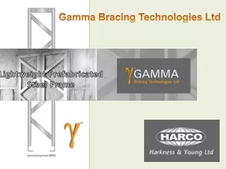
Types of Braces • Wood not recommended • Concrete tilt braces or approved equal • Note: Braces must stay in place until roofcomponents are installed.
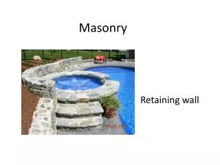
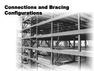
Intersection of Other Walls • Wall intersections may substitute for braces • Pilasters may help in spacing braces farther apart • Connection to existing walls
Adjoining Buildings Requires scaffold & braces on same side of wall • Creates additional hardship on contractors • Alternative method – use taper bolts or she bolts connecting new wall to adjacent structural wall • Require adjacent building Owner’s permission
Moving braces from one side to another • Sometimes necessary due to work by other trades • Remove braces sequentially from one side of wall to the other • MUST attach additional braces before removing existing • Adding additional coil loops may be necessary: • Will help facilitate the moving of braces while providing a good level of safety for personnel
Our Nemesis – WIND:
Our wind standard:35 mph Call the Weather Service • Obtain regional wind chart of historical data • Need to know daily wind speeds • Daily wind directions • Procure a wind meter
Establish an Action Level • At winds speeds above 25 mph: • Check that braces are secure • Consider evacuation of scaffold and surrounding areas • Our unbraced, grouted wall deflected less than an inch at 35 mph and fell at a wind speed in excess of 60 mph
In Conclusion • This is NOT intended to be used as a complete approach to bracing walls • ALL relevant factors MUST be considered • Site conditions • Weather conditions • Wall design • Construction sequence • Property lines • Any other relevant conditions or factors
References • Masonry Bracing Task Force (Funded by OR-OSHA Grant) • Task Force Documentation • TestReport • Video