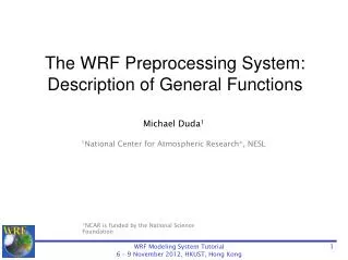
The WRF Preprocessing System: Description of General Functions
570 likes | 755 Vues
The WRF Preprocessing System: Description of General Functions. Michael Duda 1 1 National Center for Atmospheric Research*, NESL. *NCAR is funded by the Nationa l Science Foundation. Purpose of this Lecture. In this lecture, our goals are to: 1) Understand the purpose of the WPS

The WRF Preprocessing System: Description of General Functions
E N D
Presentation Transcript
The WRF Preprocessing System: Description of General Functions Michael Duda1 1National Center for Atmospheric Research*, NESL *NCAR is funded by the National Science Foundation
Purpose of this Lecture In this lecture, our goals are to: 1) Understand the purpose of the WPS 2) Learn what each component of the WPS does 3) Understand why the components work as they do - The details of actually running the WPS are covered in a lecture this afternoon
Purpose of the WPS The purpose of the WPS is to prepare input to WRF for real-data simulations: • Defines simulation coarse domain and nested domains • Computes latitude, longitude, map scale factors, and Coriolis parameters at every grid point • Interpolates time-invariant terrestrial data to simulation grids (e.g., terrain height and soil type) • Interpolates time-varying meteorological fields from another model onto simulation domains
The geogrid program geogrid: think geographical
The geogrid program • For WRF model domains, geogrid defines: • Map projection (all domains must use the same projection) • Geographic location of domains • Dimensions of domains • Geogrid provides values for static (time-invariant) fields at each model grid point • Compute latitude, longitude, map scale factor, and Coriolis parameters at each grid point • Horizontally interpolate static terrestrial data (e.g., topography height, land use category, soil type, vegetation fraction, monthly surface albedo)
Geogrid: Defining model domains • First, we choose a map projection to use for the domains; why? • The real earth is (roughly) an ellipsoid • But WRF computational domains are defined by rectangles in the plane • ARW can use any of the following projections: • Lambert conformal • Mercator • Polar stereographic • Latitude-longitude (for global domain, you must choose this projection!)
ARW Projections: Lambert Conformal • Well-suited for mid-latitudes • Domain cannot contain either pole • Domain cannot be periodic in west-east direction • Either one or two true latitudes may be specified • If two are given, the order doesn’t matter
ARW Projections: Mercator • Well-suited for low-latitudes • May be used for “channel” domain (periodic domain in west-east direction) • A single true latitude is specified • Cylinder intersects the earth’s surface at +/- truelat
ARW Projections: Polar Stereographic • Good for high-latitude domains, especially if domain must contain a pole • A single true latitude is specified
ARW Projections: Cylindrical Equidistant • Required for global domains • May be used for regional domains • Can be used in its normal or rotated aspect
Rotating the Lat-lon Grid In certain cases, it may be desirable or necessary to rotate the poles of the projection away from the poles of the earth • When placing a nest over a region that would otherwise lie within a filtered region • When using the lat-lon projection for limited area grids See p. 3-12
Geogrid: Defining Model Domains • Define projection of domains using a subset of the following parameters • MAP_PROJ: ‘lambert’, ‘mercator’, ‘polar’, or ‘lat-lon’ • TRUELAT1: First true latitude • TRUELAT2: Second true latitude (only for Lambert conformal) • POLE_LAT, POLE_LON: Location of North Pole in WRF computational grid (only for ‘lat-lon’) • STAND_LON: The meridian parallel to y-axis • All parameters reside in the file namelist.wps See p. 3-9 and 3-43
Geogrid: Defining Model Domains • Define the area covered (dimensions and location) by coarse domain using the following: • REF_LAT, REF_LON: The (lat,lon) location of a known location in the domain (by default, the center point of the domain) • DX, DY: Grid distance where map factor = 1 • For Lambert, Mercator, and polar stereographic: meters • For (rotated) latitude-longitude: degrees • E_WE: Number of velocity points in west-east direction • E_SN: Number of velocity points in south-north direction See p. 3-13 and 3-42
Geogrid: Defining ARW Domains In ARW, (REF_LAT, REF_LON) can refer to an arbitrary point in the domain by using the variables REF_X and REF_Y See p. 3-44
Geogrid: Nesting Basics • A nested domain is a domain that is wholly contained within its parent domain and that receives information from its parent, and that may also feed information back to its parent • A nested domain has exactly one parent • A domain may have one or more children • 2-way nests on the same nesting level must not overlap in coverage!
Geogrid: Nesting Example Example configuration – 4 domains Each domain is assigned a domain ID # 1 Nesting level 1 2 4 Nesting level 2 3 Nesting structure shown as a tree for the domains at left
Geogrid: Defining Nested Domains • Define the dimensions and location of nested domains using: • PARENT_ID: Which domain is the parent? • PARENT_GRID_RATIO: What is the ratio of grid spacing in parent to grid spacing in this nest? • I_PARENT_START: i-coordinate in parent of this nest’s lower-left corner • J_PARENT_START: j-coordinate in parent of this nest’s lower-left corner • E_WE: Number of velocity points in west-east direction • E_SN: Number of velocity points in south-north direction See p. 3-20 and 3-42
Geogrid: Defining Nested Domains The grid spacing (dx) of domain 2 is determined by grid spacing of domain 1 and the parent_grid_ratio
Geogrid: Nesting example Assuming parent_grid_ratio = 3 In ARW, nest dimensions must be (n*parent_grid_ratio + 1) for some integer n 112 = 3*n+1 for n=37 97 = 3*n+1 for n=32
Geogrid: Interpolating Static Fields • Given definitions of all computational grids, geogrid interpolates terrestrial, time-invariant fields • Topography height • Land use categories • Soil type (top layer & bottom layer) • Annual mean soil temperature • Monthly vegetation fraction • Monthly surface albedo
Geogrid: Interpolating Static Fields Input data on lat/lon grid WRF grid In general, source data are given on a different projection from the model grid
Geogrid: Interpolation Options • 4-point bilinear • 16-point overlapping parabolic • 4-point average (simple or weighted) • 16-point average (simple or weighted) • Grid cell average • Nearest neighbor • Breadth-first search See p. 3-55
Why have so many interpolation options? • Different interpolators work best for different fields and different relative grid resolutions • Some interpolators preserve positive definiteness • Some interpolators produce “smoother” fields • Some interpolators are best suited for discrete or categorical fields • Some are good when going from a fine grid to a coarse grid • Having a choice of how to interpolate fields is good! • We will see examples of this in the Advanced WPS Usage talk on Thursday!
Geogrid: Program Flexibility • The GEOGRID.TBL file determines • Which fields will be produced by geogrid • What sources of data will be used • How the data will be interpolated/smoothed • Any derived fields (e.g., dominant cat., df/dx) • Acceptable defaults exist in GEOGRID.TBL, so user will not generally need to edit the file
Geogrid: Program Flexibility • geogrid is flexible enough to ingest and interpolate new static fields • handles either continuous or categorical fields • New data sets must be written to simple binary format • User needs to add an entry to the file GEOGRID.TBL
Geogrid: Program Output • The parameters defining each domain, plus interpolated static fields, are written using the WRF I/O API • One file per domain for ARW • Filenames: geo_em.d0n.nc (where n is the domain ID #) • Example: geo_em.d01.nc geo_em.d02.nc (nest) geo_em.d03.nc (nest)
Geogrid: Example Output Fields LAND-SEA Mask Topography Height Top-layer Soil Category Vegetation Fraction (July)
The ungrib program ungrib: think un+grib
What is a GRIB file, anyway? • GRIB is a WMO standard file format for storing regularly-distributed (e.g., gridded) fields • “General Regularly-distributed Information in Binary” • Fields within a GRIB file are compressed with a lossy compression • Think of truncating numbers to a fixed number of digits • A record-based format • Fields in a file are identified only by code numbers • These numbers must be referenced against an external table to determine the corresponding field
The ungrib program • Read GRIB Edition 1 and GRIB Edition 2 files • Extract meteorological fields • If necessary, derive required fields from related ones • E.g., Compute RH from T, P, and Q • Write requested fields to an intermediate file format
Ungrib: Vtables How does ungrib know which fields to extract? Using Vtables (think: Variable tables) • Vtables are files that give the GRIB codes for fields to be extracted from GRIB input files • One Vtable for each source of data • Vtables are provided for: NAM 104, NAM 212, GFS, AGRMET, and others
Ungrib: Example Vtable GRIB1| Level| From | To | UNGRIB | UNGRIB | UNGRIBParam| Type |Level1|Level2| Name | Units | Description-----+-----+-----+-----+---------+--------+---------------------------------------- 11 | 100 | * | | T | K | Temperature 33 | 100 | * | | U | m s-1 | U 34 | 100 | * | | V | m s-1 | V 52 | 100 | * | | RH | % | Relative Humidity 7 | 100 | * | | HGT | m | Height 11 | 105 | 2 | | T | K | Temperature at 2 m 52 | 105 | 2 | | RH | % | Relative Humidity at 2 m 33 | 105 | 10 | | U | m s-1 | U at 10 m 34 | 105 | 10 | | V | m s-1 | V at 10 m 1 | 1 | 0 | | PSFC | Pa | Surface Pressure 130 | 102 | 0 | | PMSL | Pa | Sea-level Pressure 144 | 112 | 0 | 10 | SM000010 | kg m-3 | Soil Moist 0-10 cm below grn layer (Up) 144 | 112 | 10 | 40 | SM010040 | kg m-3 | Soil Moist 10-40 cm below grn layer 144 | 112 | 40 | 100 | SM040100 | kg m-3 | Soil Moist 40-100 cm below grn layer 144 | 112 | 100 | 200 | SM100200 | kg m-3 | Soil Moist 100-200 cm below gr layer 85 | 112 | 0 | 10 | ST000010 | K | T 0-10 cm below ground layer (Upper) 85 | 112 | 10 | 40 | ST010040 | K | T 10-40 cm below ground layer (Upper) 85 | 112 | 40 | 100 | ST040100 | K | T 40-100 cm below ground layer (Upper) 85 | 112 | 100 | 200 | ST100200 | K | T 100-200 cm below ground layer (Bottom) 91 | 1 | 0 | | SEAICE | proprtn | Ice flag 81 | 1 | 0 | | LANDSEA | proprtn | Land/Sea flag (1=land,2=sea in GRIB2) 7 | 1 | 0 | | HGT | m | Terrain field of source analysis 11 | 1 | 0 | | SKINTEMP | K | Skin temperature (can use for SST also) 65 | 1 | 0 | | SNOW | kg m-2 | Water equivalent snow depth 223 | 1 | 0 | | CANWAT | kg m-2 | Plant Canopy Surface Water 224 | 1 | 0 | | SOILCAT | Tab4.213| Dominant soil type category 225 | 1 | 0 | | VEGCAT | Tab4.212| Dominant land use category-----+-----+-----+-----+---------+--------+----------------------------------------
Ungrib: GRIB2 Vtable Entries |metgrid |GRIB2|GRIB2|GRIB2|GRIB2|| Description |Discp|Catgy|Param|Level|+-----------------------------------------+-----------------------+| Temperature | 0 | 0 | 0 | 100 || U | 0 | 2 | 2 | 100 || V | 0 | 2 | 3 | 100 || Relative Humidity | 0 | 1 | 1 | 100 || Height | 0 | 3 | 5 | 100 || Temperature at 2 m | 0 | 0 | 0 | 103 || Relative Humidity at 2 m | 0 | 1 | 1 | 103 || U at 10 m | 0 | 2 | 2 | 103 || V at 10 m | 0 | 2 | 3 | 103 || Surface Pressure | 0 | 3 | 0 | 1 || Sea-level Pressure | 0 | 3 | 1 | 101 || Soil Moist 0-10 cm below grn layer (Up) | 2 | 0 | 192 | 106 || Soil Moist 10-40 cm below grn layer | 2 | 0 | 192 | 106 || Soil Moist 40-100 cm below grn layer | 2 | 0 | 192 | 106 || Soil Moist 100-200 cm below gr layer | 2 | 0 | 192 | 106 || Soil Moist 10-200 cm below gr layer | 2 | 0 | 192 | 106 || T 0-10 cm below ground layer (Upper) | 0 | 0 | 0 | 106 || T 10-40 cm below ground layer (Upper) | 0 | 0 | 0 | 106 || T 40-100 cm below ground layer (Upper) | 0 | 0 | 0 | 106 || T 100-200 cm below ground layer (Bottom)| 0 | 0 | 0 | 106 || T 10-200 cm below ground layer (Bottom) | 0 | 0 | 0 | 106 || Ice flag | 0 | 2 | 0 | 1 || Land/Sea flag (1=land, 0 or 2=sea) | 2 | 0 | 0 | 1 || Terrain field of source analysis | 2 | 0 | 7 | 1 || Skin temperature (can use for SST also) | 0 | 0 | 0 | 1 || Water equivalent snow depth | 0 | 1 | 13 | 1 || Dominant soil type cat.(not in GFS file)| 2 | 3 | 0 | 1 || Dominant land use cat. (not in GFS file)| 2 | 0 | 198 | 1 |+-----------------------------------------+-----------------------+
Ungrib: Vtables What if a data source has no existing Vtable? Create a Vtable • Get a listing of GRIB codes for fields in the source • Check documentation from originating center or use utility such as wgrib, g1print, g2print • Use existing Vtable as a template • Check documentation in Chapter 3 of the Users’ Guide for more information about Vtables See p. 3-35
Ungrib: Intermediate File Format • After extracting fields listed in Vtable, ungrib writes those fields to intermediate format • For meteorological data sets not in GRIB format, the user may write to intermediate format directly • Allows WPS to ingest new data sources; basic programming required of user • Simple intermediate file format is easily read/written using routines from WPS (read_met_module.F and write_met_module.F) See p. 3-33
Ungrib: Program Output • Output files named FILE:YYYY-MM-DD_HH • YYYY is year of data in the file; MM is month; DD is day; HH is hour • All times are UTC • Example: FILE:2007-07-24_00 FILE:2007-07-24_06 FILE:2007-07-24_12 ungrib can also write intermediate files in the MM5 or WRF SI format! (To allow for use of GRIB2 data with MM5, for example)
Ungrib: Obtaining GRIB Data • Where does one get GRIB data? • User’s responsibility • Some free data are available from NCAR and NCEP. See • http://www.mmm.ucar.edu/wrf/users/ > under the “Downloads” tab: • Some NCEP data in the past year • NCEP operational data available daily
The metgrid program metgrid: think meteorological
The metgrid program • Horizontally interpolate meteorological data (extracted by ungrib) to simulation domains (defined by geogrid) • Masked interpolation for masked fields • Rotate winds to WRF grid • i.e., rotate so that U-component is parallel to x-axis, V-component is parallel to y-axis
Metgrid: ARW Grid Staggering • For ARW, wind U-component interpolated to “u” staggering • Wind V-component interpolated to “v” staggering • Other meteorological fields interpolated to “θ” staggering by default (can change this!) v A single ARW grid cell, with “u”, “v”, and “θ” points labeled. u u θ v
Metgrid: Interpolation Options* • 4-point bilinear • 16-point overlapping parabolic • 4-point average (simple or weighted) • 16-point average (simple or weighted) • Grid cell average • Nearest neighbor • Breadth-first search * These are the same options available for geogrid!
Metgrid: Masked Interpolation • Masked fields may only have valid data at a subset of grid points • E.g., SST field only valid on water points • When metgrid interpolates masked fields, it must know which points are invalid (masked) • Can use separate mask field (e.g., LANDSEA) • Can rely on special values (e.g., 1×1030) in field itself to identify masked grid points
Metgrid: Masked Interpolation • Suppose we need to interpolate to point X • Using red points as valid data can give a bad interpolated value! • Masked interpolation only uses valid blue points to interpolate to X = valid source data = masked/invalid data Not every interpolation option can handle masked points; Chapter 3 of the ARW Users’ Guide provides more details
Example: Masked Interpolation Skin temperature field interpolated using masks: GFS water points interpolated to model water points, GFS land points interpolated to model land points. Skin temperature field interpolated from GFS 0.5-deg field with no mask using a sixteen-point interpolator.
Metgrid: Wind Rotation • Input wind fields (U-component + V-component) are either: • Earth-relative: U-component = westerly component; V-component = southerly component • Relative to source grid: U-component (V-component) parallel to source model x-axis (y-axis) • WRF expects wind components to be relative to the simulation grid
Metgrid: Wind Rotation Example A wind vector, shown in terms of its U and V components with respect to the source grid. The same vector, in terms of its U and V components with respect to the WRF simulation grid. This process may require two rotations: one from source grid to earth grid and a second from earth grid to WRF grid
Metgrid: Constant Fields • For short simulations, some fields may be constant • E.g., SST or sea-ice fraction • Use namelist option CONSTANTS_NAME option to specify such fields: • CONSTANTS_NAME = 'SST_FILE:2007-07-24_00'