Download
1 / 59
690 likes | 1.24k Vues
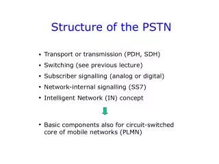
Structure of the PSTN. Transport or transmission (PDH, SDH) Switching (see previous lecture) Subscriber signalling (analog or digital) Network-internal signalling (SS7) Intelligent Network (IN) concept Basic components also for circuit-switched core of mobile networks (PLMN).

E N D
Structure of the PSTN • Transport or transmission (PDH, SDH) • Switching (see previous lecture) • Subscriber signalling (analog or digital) • Network-internal signalling (SS7) • Intelligent Network (IN) concept • Basic components also for circuit-switched core of mobile networks (PLMN)
Basic functional parts of the PSTN PSTN Switching in exchanges Transmission (PDH, SDH) Databases in the network (HLR) Subscriber signalling (analog or ISDN=DSS1) Network-internal signalling (SS7)
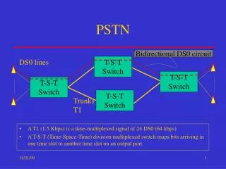
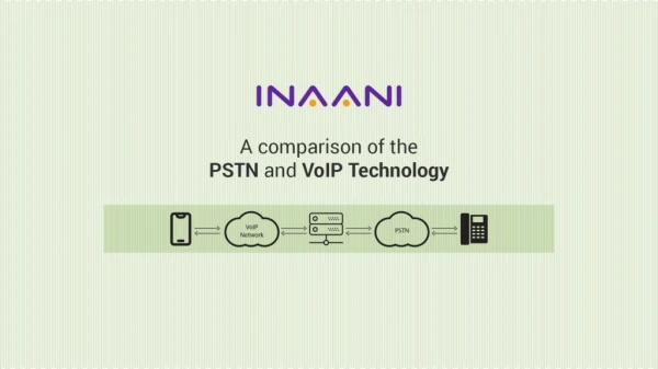
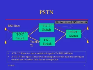
PSTN Circuit-switched technology Circuit-switched network Packet-switched network Based on 64 kbit/s channels (TDM time slots) Time Division Multiplexing (TDM) Connection-oriented operation (setup & release connection => call) Charging is based on time duration of connection Optimized for delay-sensitive services (speech) No fixed channel concept (bit rate is not constant) Statistical multiplexing (greater flexibility) Connectionless operation (independent routing of packets) as default More flexible charging solutions QoS solutions required for delay-sensitive services
IP network as alternative to PSTN Voice traffic can naturally also be carried over Packet-switched (IP) networks. This topic is covered in a future lecture. PSTN Switching in exchanges Transmission (PDH, SDH) Databases in the network (HLR) Subscriber signalling (analog or ISDN=DSS1) Network-internal signalling (SS7) IP network Quality-of-Service (QoS) support needed!
Transmission: PDH or SDH systems PSTN Switching in exchanges Transmission (PDH, SDH) Databases in the network (HLR) Subscriber signalling (analog or ISDN=DSS1) Network-internal signalling (SS7)
64 kbit/s channel (or TDM time slot) This is the basic transport unit in both PDH and SDH transport systems. Note that switching in exchanges in the PSTN is also based on 64 kbit/s TDM time slots. When used for voice transport, a 64 kbit/s channel contains PCM (Pulse Code Modulation) speech, generated according to ITU-T specification G.711. Analog speech signal (300…3400 Hz) Sampling produces 8000 samples/s Each sample is encoded into an 8-bit PCM code word (e.g. 01100101) time => 8000 x 8 bit/s
PDH and SDH transmission bit rates PDH (Plesiochronous Digital Hierarchy) Japan USA Europe J1 1.5 Mbit/s T1 1.5 Mbit/s E1 2 Mbit/s J2 6 T2 6 E2 8 J3 32 T3 45 E3 34 J4 98 T4 140 E4 140 SONET (North Am.) SDH STS-1 51.84 Mbit/s STS-3 155.52 STM-1 STS-12 622.08 STM-4 STS-48 2.488 Gbit/s STM-16
Structure of E1 frame (2.048 Mbit/s) 0 1 2 16 31 32 TDM time slots (with 8 bits each / frame) Time slots 1-31 carry digital signals (usually PCM speech) with a bitrate of 64 kbit/s. Time slot 0 is used for frame synchronization: received bit stream ... where does a new frame begin? ... ... Time slot 16 usually contains SS7 signalling information.
Structure of STM-1 frame in SDH 9 261 bytes STM-1 payload (contains the actual information) SOH SOH STM = Synchronous transport module SOH = Section overhead AU = Administrative unit 3 1 AU pointer indicates where the virtual container starts in the payload field 5 Higher-order STM-4 signal is generated using synchronous byte interleaving: byte from first STM-1 signal … byte from second STM-1 signal byte from third STM-1 signal … byte from fourth STM-1 signal
Bitrate of STM-1 signal 9 261 bytes STM-1 payload SOH SOH Basic idea: bytes from a 64 kbit/s channel are carried in successive STM-1 frames (exactly one byte per frame). 3 1 5 STM-1 frame contains 9 x 270 bytes => bitrate of STM-1 signal: 9 x 270 x 64 kbit/s = 155.52 Mbit/s
Mapping into STM-1 frames SOH SOH AU-4 pointer points to first byte of VC VC-4 (Virtual container) P O H 9 Virtual container “floats” within the payload of STM-1 frames POH = Path overhead 1 260 bytes
Filling of STM-1 payload in practice In reality, the STM-1 payload is filled like this: P Beginning of virtual container STM-1 frame N Path overhead bytes P Beginning of next virtual container STM-1 frame N+1
SDH pointer adjustment (1) When VC-4 clock rate is larger than STM-1 clock rate => pointer value is shifted forward three bytes SOH SOH old new Pointer value updated VC-4(Virtual container) Three “empty” bytes are inserted here
SDH pointer adjustment (2) When VC-4 clock rate is smaller than STM-1 clock rate => pointer value is shifted back three bytes SOH STM-1 payload old new Pointer value updated VC-4(Virtual container) AU-4 pointer Three VC bytes are stored here
Payload mapping STM-1 can carry 63 E1 signals. SDH systems nowadays also carry ATM and IP traffic. STM-1
More about SDH… SDH pocket guide (there is a link to this material on the course home page) www.iec.org/online/tutorials/sdh Section 4.4.1 in ”Understanding Telecommunications 1” by Ericsson Telecom, Telia and Studentlitteratur 1998 (the corresponding online course is sometimes available at www.ericsson.com)
Subscriber signalling PSTN Switching in exchanges Transmission (PDH, SDH) Databases in the network (HLR) Subscriber signalling (analog or ISDN=DSS1) Network-internal signalling (SS7)
Analog subscriber signalling The calling party (user A) tells the local exchange to set up (disconnect) a call by generating a short (open) circuit in the terminal => off-hook (on-hook) operation. The dialled called party (user B) number is sent to the local exchange in form of Dual Tone Multi-Frequency (DTMF) signal bursts. Alerting (ringing) means that the local exchange sends a strong sinusoid to the terminal of user B. In-channel information in form of audio signals (dial tone, ringback tone, busy tone) is sent from local exchange to user. User can send DTMF information to network. 1 2 3 4
Analog subscriber signalling in action User A LE A LE B User B SS7 signalling (ISUP) LE = local exchange Off-hook Dial tone B number Ringing signal Ringback tone (or busy tone) Off-hook (user B answers) Connection established
ISDN subscriber signalling in action User A LE A LE B User B SS7 signalling (ISUP) Off-hook DSS1 signalling messages Setup B number Setup Call proc Ringing Alert Tones generated in terminal Alert Off-hook (user B answers) Conn Conn Connection established
What does ISDN originally mean? 1. End-to-end digital connectivity 2. Enhanced subscriber signaling 3. A wide variety of new services (due to 1 and 2) 4. Standardized access interfaces and terminals Idea originated in the 1980’s ISDN is not a “new” network separated from the PSTN. Interworking with “normal” PSTN equipment is very important. interaction is possible ISDN terminal PSTN terminal
PSTN vs. ISDN user access 300 … 3400 Hz analog transmission band “Poor-performance” subscriber signaling PSTN 2 x 64 kbit/s digital channels (B channels) 16 kbit/s channel for signaling (D channel) => Digital Subscriber Signalling system nr. 1 (DSS1) Basic Rate Access ISDN 30 x 64 kbit/s digital channels (B channels) 64 kbit/s channel for signaling (D channel) Mainly used for connecting private branch exchanges (PBX) to the PSTN. Primary Rate Access ISDN
End-to-end digital signalling User interface PSTN Network User interface Q.931 Q.931 ISUP ISUP Q.931 Q.931 SS7 DSS1 MTP 3 MTP 3 DSS1 Q.921 Q.921 MTP 2 MTP 2 Q.921 Q.921 I.430 I.430 MTP 1 MTP 1 I.430 I.430 contains the signalling messages for call control
Signalling System nr. 7 (SS7) PSTN Switching in exchanges Transmission (PDH, SDH) Databases in the network (HLR) Subscriber signalling (analog or ISDN=DSS1) Network-internal signalling (SS7)
History of inter-exchange signalling Before 1970, only channel-associated signalling (CAS) was used. In CAS systems, the signalling is carried in-band along with the user traffic. CAS SS6 = CCIS (common channel interoffice signaling) was deployed in North America as an interim solution, but not in Europe. CCIS is not the same thing as SS7. CCIS Starting from 1980 (mainly in Europe), CAS was being replaced by SS7. The use of stored program control (SPC) exchanges made this possible. Like CCIS, signalling messages are transmitted over separate signalling channels. Unlike CCIS, SS7 technology is not monolithic, but based on protocol stacks. SS7
Channel-associated signalling (CAS) CAS means in-band signalling over the same physical channels as the circuit-switched user traffic (e.g. voice). Signalling is possible Exchange Exchange Exchange Signalling is not possible before previous circuit-switched link is established Circuit switched connection CAS has two serious draw-backs: Setting up a circuit switched connection is very slow. Signalling to/from databasesis not feasible in practice(setting up a circuit switched connection to the database and then releasing it would be extremely inconvenient).
Common channel signalling (CCS) In practice, CCS = SS7. Signalling is possible anywhere anytime Exchange Exchange Database The packet-switched signalling network is totally separated from the circuit-switched connections. Consequently: Signalling to/from databases is possible anytime. End-to-end signallingis possible before call setup and also during the conversation phase of a call. There is one drawback: It is difficult to check if the circuit-switched connections are really working (= continuity check).
Signalling example Tokyo Oulu Exch User A (calling user) User B (called user) Exch Exch London Database A typical scenario: User A calls mobile user B. The call is routed to a specific gateway exchange (GMSC) that must contact a database (HLR) to find out under which exchange (MSC) the mobile user is located. The call is then routed to this exchange.
Protocol layers (“levels”) of SS7 ISDN User Part (ISUP) Application protocols (e.g. Mobile Application Part, MAP) Transaction Capabilities Application Part (TCAP) SS7 application protocol for managing circuit-switched connections Signalling Connection Control Part (SCCP) MTP user MTP level 3 (routing in the signalling network) MTP MTP level 2 (link-layer protocol) MTP level 1 (64 kbit/s PCM time slot)
SS7 protocols vs. OSI model SS7 protocol stack OSI protocol layer model … ISUP MAP Application TCAP Presentation Session Transport SCCP Network MTP level 3 MTP level 2 Data link MTP level 1 Physical
OSI protocol layer model User application (in this case, the actual signalling messages) Application layer Presentation layer Data compression & coding Session layer Dialogue control End-to-end flow & error control Transport layer Switching & routing through the communications network Network layer Data link layer Link-layer flow & error control Multiplexing & transport of bits, time slots inPDH or SDH systems Physical layer
Message Trasfer Part (MTP) functions MTP level 1 (signalling data link level): Digital transmission channel (64 kbit/s TDM time slot) MTP level 2 (signalling link level): Frame-based protocol for flow control, error control (using Automatic Repeat reQuest, ARQ), and signalling network supervision and maintenance functions. MTP level 3 (signalling network level): Routing in the signalling network between signalling points (using signalling point codes). MTP level 3 ”users” are ISUP and SCCP (other ”users” such as TUP or DUP are not widely used any more).
MTP level 2 frame formats Level 3 user information MSU (Message Signal Unit) F CK SIF SIO LI Control F • Network: • National • International • User part: • ISUP • SCCP • Signalling • network • management LSSU (Link Status Signal Unit) F CK SF LI Control F FISU (Fill-In Signal Unit) F CK LI Control F LSB MSB
MTP level 2 frames • MSU (Message Signal Unit): • Contains actual SS7 signalling messages • The received frame is MSU if LI > 2 • (LI = number of octets) • LSSU (Link Status Signal Unit): • Contains signalling messages for MTP level 2 (signalling link) supervision • The received frame is LSSU if LI = 1 or 2 • FISU (Fill-In Signal Unit): • Can be used to monitor quality of signalling link at receiving end • The received frame is FISU if LI = 0
Signalling points (SP) in SS7 Network elements (relevant from signalling point of view) contain signalling points identified by unique signalling point codes. Signalling Transfer Points only relay signalling messages STP STP Signalling Point (in a database, such as HLR in mobile network) SP MAP STP Exchange SP Signalling Point (signalling termination in an exchange) ISUP
Signalling point code (SPC) SS7 signalling messages contain MTP level 3 routing information in the form of a routing label: MSB LSB International (and most national) signalling networks (ITU-T): 14-bit Destination Point Code (DPC) 14-bit Originating Point Code (OPC) 4-bit Signalling Link Selection (SLS) North American national signalling network (ANSI): 24-bit DPC and OPC, 5-bit SLS code SIO octet DPC DPC OPC OPC OPC SLS Signalling message payload Format for international SPC: For examples, see:www.numberingplans.com Zone Area/Network SP 3 bits 8 bits 3 bits
F CK SIF SIO LI Control F Same SPCs can be reused at different network levels International SPC = 277 SPC = 277 National SPC = 277 means different signalling points (network elements) at different network levels. The Service Information Octet (SIO) indicates whether the DPC and OPC are international or national signalling point codes.
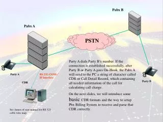
ISDN User Part (ISUP) ISUP is a signalling application protocol that is used for establishing and releasing circuit-switched connections (calls). Only for signalling between exchanges (ISUP can never be used between an exchange and a stand-alone database) Not only for ISDN (=> ISUP is generally used in the PSTN) Structure of ISUP message: SIO (one octet) Routing label (four octets) CIC (two octets) Must always be included in ISUP message Message type (one octet) Mandatory fixed part E.g., IAM message Mandatory variable part E.g., contains called (user B) number in IAM message Optional part
ISUP signalling messages Basic ISUP signalling messages: Call setup: IAM (Initial address message) From LE A to LE B ACM (Address complete message) From LE B to LE A ANM (Answer message) Call release: Direction depends on releasing party (user A or user B) REL (Release message) RLC (Release complete message)
Difference between SLS and CIC The four-bit signalling link selection (SLS) field in the routing labeldefines the signalling link which is used for transfer of the signalling information. The 16-bit circuit identification code (CIC) contained in the ISUP messagedefines the TDM time slot or circuit with which the ISUP message is associated. Signalling link STP Exchange Exchange Circuit
Signalling using IAM message STP STP SL 4 SL 7 Exchange SPC = 82 Exchange SPC = 22 Exchange SPC = 60 Circuit 20 Circuit 14 Processing in (transit) exchange(s): Received IAM message contains B-number. Exchange performs number analysis (not part of ISUP) and selects new DPC (60) and CIC (20). Outgoing message: OPC = 82 CIC = 14 DPC = 22 SLS = 4
Setup of a call using ISUP User A LE A Transit exchange LE B User B Setup IAM IAM Setup DSS1 signalling assumed Number analysis Alert ACM ACM Alert Connect ANM ANM Connect Charging of call starts now
Call setup: Signalling sequence 1 User A LE A TE LE B User B Off hook Local exchange detects setup request and returns dial tone Dial tone B number • Local exchange: • analyzes B number • determines that call should be routed via transit exchange (TE)
Call setup: Signalling sequence 2 User A LE A TE LE B User B Initial address message (IAM) ISUP message IAM is sent to transit exchange (TE). TE analyzes B number and determines that call should be routed to local exchange of user B (LE B). IAM message is sent to LE B. There now exists a circuit-switched path (the path is “cut through”) between user A and LE B.
Call setup: Signalling sequence 3 User A LE A TE LE B User B Address complete message (ACM) Ringing signal Ringback tone or Ringing signal is sent to user B (=> user B is alerted). Ringback tone (or busy tone) is sent to user A. (Ringback/busy tone is generated locally at LE A or is sent from LE B through circuit switched path.)
Call setup: Signalling sequence 4 Conversation over this “pipe” User A LE A TE LE B User B User B answers Charging starts now Answer message (ANM) User B answers, connection is cut through at LE B. Charging of the call starts when ISUP message ANM is received at LE A (the normal case). The 64 kbit/s bi-directional circuit switched connection is now established.
E.164 numbering scheme In each exchange, the B number is analyzed at call setup (after the IAM message containing the number has been received) and a routing program (not part of ISUP) selects the next exchange to which the call is routed. 00 358 9 1234567 International number 0 9 1234567 National number 1234567 User number Prefix Country code 358 Area code 9 or mobile network code, e.g. 40
E.164 number structure Max. 15 digits 00 358 9 1234567 Prefix Subscriber number Country code (1-3 digits) National destination code (1-3 digits) Area code, e.g. 9 Mobile network code, e.g. 40 For examples, see:www.numberingplans.com MSISDN number
Conversation over this “pipe” Signalling sequence for call release User A LE A TE LE B User B On hook Release message (REL) Charging stops Release complete message (RLC) The circuits between exchanges are released one by one. (The generation of “hanging circuits” should be avoided, since these are blocked from further use.)
Signalling Connection Control Part (SCCP) SCCP is required when signalling information is carried between exchanges and databases in the network. An important task of SCCP is global title translation (GTT): STP with GTT capability Exchange STP Database 1. Exchange knows the global title (e.g. 0800 number or IMSI number in a mobile network) but does not know the DPC of the database related to this global title. SCCP performs global title translation in the STP (0800 or IMSI number => DPC) and the SCCP message can now be routed to the database. 2.