COE 202: Digital Logic Design Memory and Programmable Logic Devices
COE 202: Digital Logic Design Memory and Programmable Logic Devices. Courtesy of Dr. Ahmad Almulhem. Objectives. Memory Programmable Logic Devices (PLD). Memory.

COE 202: Digital Logic Design Memory and Programmable Logic Devices
E N D
Presentation Transcript
KFUPM COE 202: Digital Logic DesignMemory and Programmable Logic Devices Courtesy of Dr. Ahmad Almulhem
KFUPM Objectives • Memory • Programmable Logic Devices (PLD)
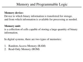
KFUPM Memory • Memory: A collection of cells capable of storing binary information (1s or 0s) – in addition to electronic circuit for storing (writing) and retrieving (reading) information. • n data lines (input/output) • k address lines • 2k words (data unit) • Read/Write Control • Memory size = 2k X n
KFUPM Memory (cont.) • Two Types of Memory: • Random Access Memory (RAM): • Write/Read operations • Volatile: Data is lost when power is turned off • Read Only Memory (ROM): • Read operation (no write) • Non-Volatile: Data is permanent. • PROM is programmable (allow special write)
KFUPM Programmable Logic Devices • Programmable Logic Device (PLD) is an integrated circuit with internal logic gates and/or connections that can in some way be changed by a programming process • Examples: • PROM • Programmable Logic Array (PLA) • Programmable Array Logic (PAL) device • Complex Programmable Logic Device (CPLD) • Field-Programmable Gate Array (FPGA) • A PLD’s function is not fixed • Can be programmed to perform different functions
KFUPM Why PLDS? • Fact: • It is most economical to produce an IC in large volumes • But: • Many situations require only small volumes of ICs • Many situations require changes to be done in the field, e.g. Firmware of a product under development • A programmable logic device can be: • Produced in large volumes • Programmed to implement many different low-volume designs
KFUPM PLD Hardware Programming Technologies • In the Factory - Cannot be erased/reprogrammed by user • Mask programming (changing the VLSI mask) during manufacturing • Programmable only once • Fuse • Anti-fuse • Reprogrammable (Erased & Programmed many times) • Volatile - Programming lost if chip power lost • Single-bit storage element • Non-Volatile - Programming survives power loss • UV Erasable • Electrically Erasable • Flash (as in Flash Memory)
KFUPM array logic symbol conventional symbol Used symbol in PLD • Most PLD technologies have gates with very high fan-in • Fuse map: graphic representation of the selected connections There is a connection There is no connection Multi-input OR gate
KFUPM Fixed AND array (decoder) Programmable OR array Programmable connections Inputs Outputs Programmable read-only memory (PROM) Programmable AND array Fixed OR array Programmable connections Inputs Outputs Programmable array logic (PAL) device Programmable AND array Programmable OR array Programmable connections Programmable connections Inputs Outputs Programmable logic array (PLA) Programmable Logic Devices (PLDs) All use AND-OR structure- differ in which is programmable
KFUPM 2kx n ROM k inputs (address) n outputs (data) Read-Only Memory (ROM) • ROM: A device in which “permanent” binary information is stored using a special device (programmer) • k inputs (address) 2k words each of size n bits (data) • ROM DOES NOT have a write operation ROM DOES NOT have data inputs Word: group of bits stored in one location
KFUPM 0 1 2 3 . . . 28 29 30 31 I0 I1 I2 I3 I4 5-to-32 decoder A7 A6 A5 A4 A3 A2 A1 A0 ROM Internal Logic • The decoder stage produces ALL possible minterms • 32 Words of 8 bits each • 5 input lines (address) • Each OR gate has a 32 input • A contact can be made using fuse/anti-fuse Internal Logic of a 32x8 ROM
KFUPM x x x x x 0 1 2 3 . . . 28 29 30 31 x x x x I0 I1 I2 I3 I4 x x x x x x x x 5-to-32 decoder x x x x x x x x x x x x x A7 A6 A5 A4 A3 A2 A1 A0 Programming a ROM • Every ONE in truth table specifies a closed circuit • Every ZERO in truth table specifies an OPEN circuit • Example: At address 00011 The word 10110010 is stored
KFUPM Combinational Circuit Implementation with ROM • ROM = Decoder + OR gates • Implementation of a combinational circuit is easy • Store the truth table by programming the ROM • Only need to provide the truth table
Example: Design a combinational circuit using ROM. The circuit accepts a 3-bit number and generates an output binary number equal to the square of the number. Solution: Derive truth table: KFUPM Example 1
B1 is ALWAYS 0 no need to generate it using the ROM B0 is equal to A0 no need to generate it using the ROM Therefore: The minimum size of ROM needed is 23X4 or 8X4 KFUPM B0 0 B1 8 X 4 ROM A0 B2 B3 A1 B4 A2 B5 Example 1 (cont.) ROM truth table – specifies the required connections
Problem: Tabulate the truth for an 8 X 4 ROM that implements the following four Boolean functions: A(X,Y,Z) = Sm(3,6,7); B(X,Y,Z) = Sm(0,1,4,5,6) C(X,Y,Z) = Sm(2,3,4); D(X,Y,Z) = Sm(2,3,4,7) Solution: KFUPM Example 2 8 X 4 ROM A X B Y C Z D
KFUPM Example 3 (Size of a ROM) • Problem: Specify the size of a ROM (number of words and number of bits per word) that will accommodate the truth table for the following combinational circuit: An 8-bit adder/subtractor with Cin and Cout. • Solution: • Inputs to the ROM (address lines) = 8 (first number) + (8 second number) + 1 (Cin) + 1 (Add/Subtract) 18 lines • Hence number of words in ROM is 218 = 256K • Size of each word = number of possible functions/outputs • = 16 (addition/subtraction) + 1 (Cout) • = 17 • Hence ROM size = 256K X 17
KFUPM Sequential Circuit Implementation with ROM Combinational Circuits • sequential circuit = combinational circuit + memory • Combinational part can be built with a ROM as shown previously • Number of address lines = No. of FF + No. of inputs • Number of outputs = No. of FF + No. of outputs inputs X outputs Z next state present state FFs
KFUPM Example • Example: Design a sequential circuit whose state table is given, using a ROM and a register. • State Table We need a 8x3 ROM (why?) 3 address lines and 3 data lines Exercise: Compare design with ROMs with the traditional design procedure.
KFUPM Types of ROMs • A ROM programmed in four different ways: • ROM: Mask Programming • By a semiconductor company • PROM (Programmable ROM) • User can blow/connect fuses with a special programming device (PROM programmer) • Only programmed once! • EPROM (Erasable PROM) • Can be erased using Ultraviolet Light • Electrically Erasable PROM (EEPROM or E2PROM) • Like an EPROM, but erased with electrical signal
KFUPM Fixed AND array (decoder) Programmable OR array Programmable connections Inputs Outputs Programmable read-only memory (PROM) Programmable AND array Fixed OR array Programmable connections Inputs Outputs Programmable array logic (PAL) device Programmable AND array Programmable OR array Programmable connections Programmable connections Inputs Outputs Programmable logic array (PLA) Other PLDs All use AND-OR structure- differ in which is programmable
KFUPM Programmable Logic Array (PLA) • AND array and OR array are programmable • XOR is available to complement an output if needed • Example: • 3 inputs/2 outputs • F1 = A B’ + A C + A’ B C’ • F2 = (AC + BC)’ Source: Mano’s textbook
Programmable Logic Array (PLA) ExampleF1(A,B,C), F2(A,B,C), PLA: (3 inputs, 4 products, 2 outputs with programmable inversion) B B • K-mapspecifications • How can thisbe implementedwith only four products? • Complete the programming table • Choose implementations (F or F) that use the largest # of shared products! • How many products needed if we implement F1 and F2? BC BC 00 01 11 10 00 01 11 10 A A 1 0 1 0 0 1 0 0 0 0 A 1 A 1 1 0 0 0 0 1 1 1 F1 map F2 map C C F A BC + A B C + A B C F AB AC +BC = = + 1 2 F AB + AC + BC + A B C = F AC AB B C = + + 1 2 PLA programming table Outputs SUM (OR) Programming Inputs Product (C) (T) term A B C F F 1 2 1 AB 1 1 1 – 1 Product (AND) Programming 1 AC 2 1 – 1 1 1 1 BC 3 – 1 1 – 1 0 0 0 4 ABC
Programmable Logic Array (PLA)Example, Contd. A B C X X X 1 X 2 X X X X X Fuse intact Fuse blown 1 X X X 3 X X 4 X X X 0 X C C B B A A 1 X F 1 F 2 The 4 products AB AC BC But we actually need F1 as an O/P, not F1- So invert F1 with the XOR ABC Implement F1 using the PLA then invert it (more economical) F2 F1
KFUPM Programmable Array Logic (PAL) • Fixed OR array and programmable AND array • Opposite of ROM • Feed back is used to support more product terms • AND output can not be shared here! • Example: • 4 inputs/4 outputs with fixed 3-input OR gates • W = A B C’ + A’ B’ C D’ • X = ? • Y = ? • Z = ? Source: Mano’s textbook
KFUPM Field Programmable Gate Array (FPGA) • Xilinx FPGAs • Configurable Logic Block (CLB) • Programmable logic and FFs • Programmable Interconnects • Switch Matrices • Horizontal/vertical lines • I/O Block (IOB) • Programmable I/O pins Source: Mano’s textbook
KFUPM More on PLDs • Read Section 6.8 in the textbook • Wikipedia/Youtube