COE 405 Programmable Logic and Storage Devices
COE 405 Programmable Logic and Storage Devices. Dr. Aiman H. El-Maleh Computer Engineering Department King Fahd University of Petroleum & Minerals. Outline. History of Computational Fabrics ASIC vs. FPGA Reconfigurable Logic Anti-Fuse-Based Approach ( Actel )

COE 405 Programmable Logic and Storage Devices
E N D
Presentation Transcript
COE 405 Programmable Logic and Storage Devices Dr. Aiman H. El-Maleh Computer Engineering Department King Fahd University of Petroleum & Minerals
Outline • History of Computational Fabrics • ASIC vs. FPGA • Reconfigurable Logic • Anti-Fuse-Based Approach (Actel) • RAM Based Field Programmable Logic (Xilinx) • CLBs • Carry & Control Logic • FPGA Memory Implementation
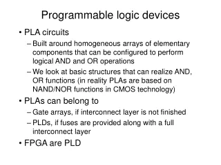
History of Computational Fabrics • Discrete devices: relays, transistors (1940s-50s) • Discrete logic gates (1950s-60s) • Integrated circuits (1960s-70s) • e.g. TTL packages: Data Book for 100’s of different parts • Gate Arrays (IBM 1970s) • Transistors are pre-placed on the chip & Place and Route software puts the chip together automatically – only program the interconnect (mask programming) • Software Based Schemes (1970’s- present) • Run instructions on a general purpose core
History of Computational Fabrics • ASIC Design (1980’s to present) • Turn Verilog directly into layout using a library of standard cells • Effective for high-volume and efficient use of silicon area • Programmable Logic (1980’s to present) • A chip that is reprogrammed after it has been fabricated • Examples: PALs, PLAs, EPROM, EEPROM, PLDs, FPGAs • Excellent support for mapping from Verilog
What is an FPGA? • A filed programmable gate array (FPGA) is a reprogrammable silicon chip. • Using prebuilt logic blocks and programmable routing resources, you can configure these chips to implement custom hardware functionality without ever having to pick up a breadboard or soldering iron. • You develop digital computing tasks in software and compile them down to a configuration file or bitstream that contains information on how the components should be wired together.
ASIC vs. FPGA FPGA FieldProgrammable GateArray ASIC ApplicationSpecific IntegratedCircuit • bought off the shelf • and reconfigured by • designers themselves • designs must be sent • for expensive and time • consuming fabrication • in semiconductor foundry • no physical layout design; • design ends with • a bitstream used • to configure a device • designed all the way • from behavioral description • to physical layout
ASIC vs. FPGA ASICs FPGAs Off-the-shelf High performance Low development cost Low power Short time to market Low cost in high volumes Reconfigurability
Other FPGA Advantages • Manufacturing cycle for ASIC is very costly, lengthy and engages lots of manpower • Mistakes not detected at design time have large impact on development time and cost • FPGAs are perfect for rapid prototyping of digital circuits • Easy upgrades like in case of software • FPGA provide a flexible platform for implementing digital computing • A rich set of macros and I/Os supported (multipliers, block RAMS, ROMS, high-speed I/O) • A wide range of applications from prototyping (to validate a design before ASIC mapping) to high performance spatial computing
How are FPGAs Used? • Prototyping • Ensemble of gate arrays used to emulate a circuit to be manufactured • Get more/better/faster debugging done than with simulation • Reconfigurable hardware • One hardware block used to implement more than one function • Special-purpose computation engines • Hardware dedicated to solving one problem (or class of problems) • Accelerators attached to general-purpose computers (e.g., in a cell phone!)
Major FPGA Vendors SRAM-based FPGAs • Xilinx, Inc. • Altera Corp. • Atmel • Lattice Semiconductor Flash & antifuse FPGAs • Actel Corp. • Quick Logic Corp. Share over 60% of the market
Actel Logic Module Example Gate Mapping Combinational Block S-R Latch
Xilinx FPGA Families • Old families • XC3000, XC4000, XC5200 • Old 0.5µm, 0.35µm and 0.25µm technology. Not recommended for modern designs. • High-performance families • Virtex (0.22µm) • Virtex-E, Virtex-EM (0.18µm) • Virtex-II, Virtex-II PRO (0.13µm) • Virtex-4 (0.09µm) • Low Cost Family • Spartan/XL – derived from XC4000 • Spartan-II – derived from Virtex • Spartan-IIE – derived from Virtex-E • Spartan-3
Two 4-input Functions, Registered Output and a Two Input Function
LUT Mapping • N-LUT direct implementation of a truth table: any function of n-inputs. • N-LUT requires 2N storage elements (latches) • N-inputs select one latch location (like a memory)
IOB Functionality • IOB provides interface between the package pins and CLBs • Each IOB can work as uni- or bi-directional I/O • Outputs can be forced into High Impedance • Inputs and outputs can be registered • advised for high-performance I/O • Inputs can be delayed
CLB Slice Structure • Each slice contains two sets of the following: • Four-input LUT • Any 4-input logic function, • or 16-bit x 1 sync RAM • or 16-bit shift register • Carry & Control • Fast arithmetic logic • Multiplier logic • Multiplexer logic • Storage element • Latch or flip-flop • Set and reset • True or inverted inputs • Sync. or async. control
Xilinx Multipurpose LUT (MLUT) 16 x 1 ROM (logic)
5-Input Functions implemented using two LUTs • One CLB Slice can implements any function of 5 inputs • Logic function is partitioned between two LUTs • F5 multiplexer selects LUT
Distributed RAM • CLB LUT configurable as Distributed RAM • A LUT equals 16x1 RAM • Implements Single and Dual-Ports • Cascade LUTs to increase RAM size • Synchronous write • Synchronous/Asynchronous read • Accompanying flip-flops used for synchronous read • Two LUTs can make • 32 x 1 single-port RAM • 16 x 2 single-port RAM • 16 x 1 dual-port RAM
Shift Register • Each LUT can be configured as shift register • Serial in, serial out • Dynamically addressable delay up to 16 cycles • For programmable pipeline • Cascade for greater cycle delays • Use CLB flip-flops to add depth
Shift Register • Register-rich FPGA • Allows for addition of pipeline stages to increase throughput • Data paths must be balanced to keep desired functionality
Fast Carry Logic • Each CLB contains separate logic and routing for the fast generation of sum & carry signals • Increases efficiency and performance of adders, subtractors, accumulators, comparators, and counters • Carry logic is independent of normal logic and routing resources • All major synthesis tools can infer carry logic for arithmetic functions
New 18 x 18 Embedded Multiplier • Embedded 18-bit x 18-bit multiplier • 2’s complement signed operation • Multipliers are organized in columns • Fast arithmetic functions • Optimized to implement multiply / accumulate modules
Design Flow - Mapping • Technology Mapping: Schematic/HDL to Physical Logic units • Compile functions into basic LUT-based groups (function of target architecture)
Design Flow – Placement & Route • Placement – assign logic location on a particular device • Routing – iterative process to connect CLB inputs/outputs and IOBs. Optimizes critical path delay – can take hours or days for large, dense designs Challenge! Cannot use full chip for reasonable speeds (wires are not ideal). Typically no more than 50% utilization.
FPGA Memory Implementation • Regular registers in logic blocks • Piggy use of resources, but convenient & fast if small • [Xilinx Vertex II] use the LUTs: • Single port: 16x(1,2,4,8), 32x(1,2,4,8), 64x(1,2), 128x1 • Dual port (1 R/W, 1R): 16x1, 32x1, 64x1 • Can fake extra read ports by cloning memory: all clones are written with the same addr/data, but each clone can have a different read address • [Xilinx Vertex II] use block ram: • 18K bits: 16Kx1, 8Kx2, 4Kx4 • with parity: 2Kx(8+1), 1Kx(16+2), 512x(32+4) • Single or dual port • Pipelined (clocked) operations