Download
1 / 19
190 likes | 327 Vues
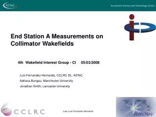
End Station A Measurements on Collimator Wakefields 4th Wakefield Interest Group - CI 05/03/2008 Luis Fernandez-Hernando, CCLRC DL, ASTeC Adriana Bungau, Manchester University Jonathan Smith, Lancaster University. Content: ESA

E N D
End Station A Measurements on Collimator Wakefields 4th Wakefield Interest Group - CI 05/03/2008 Luis Fernandez-Hernando, CCLRC DL, ASTeC Adriana Bungau, Manchester University Jonathan Smith, Lancaster University
Content: • ESA • Set up and collimators • Analysis of T480 • Results • Conclusion
Wakefields deteriorate the beam quality. • A final collimator design should minimise this effect. • Studies on wakefields generated by different collimator geometries. • Comparison to analytic predictions and simulations in order to improve both methods.
Beam Parameters at SLAC ESA and ILC *possible, using undamped beam
Ebeam=28.5GeV Magnet mover, y range = 1.4mm, precision = 1mm
T480 “wakefield box” ESA beamline ESA beamline
BPM BPM BPM BPM BPM BPM BPM BPM A run with the beam going through the middle of the collimator (or without the collimator) is used as reference for the next run where the collimator will be moved vertically. This run also serves to calculate the resolution of each BPM. The analysis will do a linear fit to the upstream and downstream BPM data separately, per each pulse (bunch) . For this fit the data is weighted using the resolution measured for each BPM.
~40 m 2 doublets ~15 m 2 triplets BPM BPM BPM BPM Vertical mover • Wakefield measurement: • Move collimators around beam (in steps of 0.2 mm, from -1.2 mm to +1.2 mm, being 0 mm the centre of the collimator). • Measure deflection from wakefields vs. beam-collimator separation
~40 m 2 doublets ~15 m 2 triplets BPM BPM BPM BPM Vertical mover • Wakefield measurement: • Move collimators around beam (in steps of 0.2 mm, from -1.2 mm to +1.2 mm, being 0 mm the centre of the collimator). • Measure deflection from wakefields vs. beam-collimator separation
BPM BPM BPM BPM The slopes of each linear fit are subtracted obtaining a deflection angle. This angle is transformed into V/pC units using the charge reading and the energy of the beam. All the reconstructed kicks are averaged per each of the different collimator positions and a cubic fit of the form: y’ = A3·y3 + A1·y + A0 is done to the result. The error in the kick reconstruction at each collimator position weights the different points for the fit. The kick factor is defined as the linear term of the cubic fit (A1).
a = 166 mrad r = 1.4 mm Col. 12 T480 (prelim.) 2007 data Angular kick (V/pC) Collimator y (mm) Data analysis Luis Fernandez - Daresbury
a = 324 mrad r = 1.4 mm Slot 2 a = 324 mrad r = 2 mm Slot 1 (r = ½ gap) Slot 3 L=1000 mm a = 324 mrad r = 1.4 mm a = p/2 r = 3.8 mm Slot 4
Measured and calculated kick factor Assuming 500 um bunch lenght Colimators 4-5 and 13-16 do not include the resistive component of the kick Note: quoted errors are estimates
SWMD: Deliverable Summary “Engineering design for ILC mechanical spoiler, including prototype evaluations of wakefield and beam-damage performance.” • Wakefields: T480 at SLAC to evaluate wakefield performance of candidate spoiler designs, benchmarking calculations/modelling • 16 jaw designs studied • Outcome of ongoing wakefield optimisation likely to require further iteration on candidate designs • First conceptual design for mechanical spoiler design available, to report at EPAC’08.