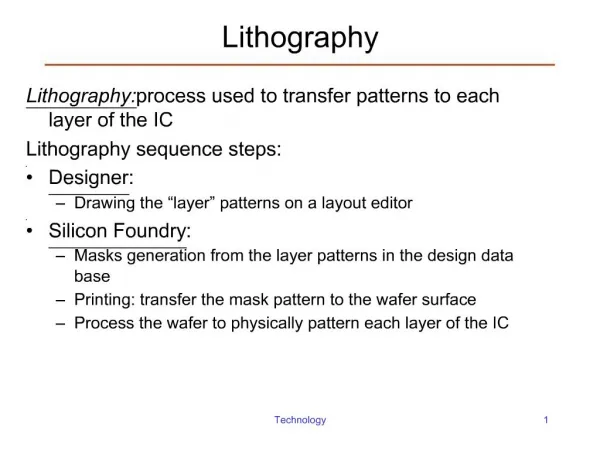
Quantum Lithography
Quantum Lithography. Robert Boyd, Sean Bentley * , Hye-Jeong Chang, Heedeuk Shin, Malcolm O’Sullivan-Hale and Kam Wai Chan Institute of Optics, University of Rochester, Rochester, NY * Department of Physics, Adelphi University, Garden City, NY Girish Agarwal

Quantum Lithography
E N D
Presentation Transcript
Quantum Lithography Robert Boyd, Sean Bentley*, Hye-Jeong Chang, Heedeuk Shin, Malcolm O’Sullivan-Hale and Kam Wai Chan Institute of Optics, University of Rochester, Rochester, NY *Department of Physics, Adelphi University, Garden City, NY Girish Agarwal Department of Physics, Oklahoma State University, Stillwater, OKHugo Cable, Jonathan Dowling Department of Physics and Astronomy, Louisiana State University, Baton Rouge, LA Presented at SPIE, August 14th, 2006
Quantum Lithography: Introduction k µ i 2  x s n = µ 2 1 ( ) ¸ I 1 ¸ + ¢ c o s  = x » i 2 m n 2 µ i 2 s n Two classical beams of light interfere…
Original Quantum Lithography Proposal j i 1 1 j i j i 2 0 0 2 + ; ; ; • Entangled photons produced in SPDC can increase resolution of an interferometric lithography system by factor of 2 (Boto et al., 2000) • N-fold enhancement possible when N photons are entangled Boto et al., PRL 85, 2733 (2000)
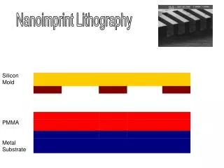
Experimental Challenges • Inconsistency? • Need strong enough light to excite two-photon absorption • Need weak enough light so that the statistics are those of individual photon pairs • Develop a multi-photon absorber • Nth harmonic generation/coincidence circuitry • Polymethylmethacrylate (PMMA) • Multi-photon absorber at visible wavelengths • e-beam resist
Quantum Lithography with an OPA • Replace parametric down-converter with high gain optical parametric amplifier (OPA) • Can be very intense • Possesses strong quantum features Agarwal, Boyd, Nagasko, Bentley, PRL 86, 1389 (2001)
Quantum Lithography with an OPA D E ^ 1 y ^ y ( ) ( ) ^ ^ b Á i i 2 2 2 ¡ + ( ) ( ) ^ h ^ h b G G ^ ^ R i i a a ¡ = 2 1 1 a c o s a e s n / a a = p 1 0 3 2 3 0 y ^ ^ ^ ^ Á i 1 ( ) ( ) ( ) b h b h ^ G G i i b ^ b i ^ ¡ ¡ i c o s e s n a a = ^ ^ b = Â 1 0 2 1 1 + 0 p a a e = 2 3 2 2 j j G E L g = p Beamsplitter Relations OPA Relations Two-photon Output
Two-Photon Excitation Rate 1 / h d I t p o o n s m o e = 3 G 0 5 5 = : • For light from an OPA, both linear and quadratic dependence are present. • Cross-over point: For cases of practical interest, the rate scales quadratically with I.
Visibility using an OPA and TPA 2 h G c o s V = 2 2 h h G G i 4 + c o s s n ( ) 2 ( ) 2 R R ¡ V i m a x m n = ( ) ( ) 2 2 R R + m a x i m n Visibility versus Gain Visibility never fallsbelow 20%
Effect of an N-Photon Absorber = N 2 p N D E ! P N y 2 ( ) X ( ) N N N N = ( ) ( ) N N N N 2 2 2 2 ¯ ¯ ¡ ¡ N ^ ^ R ( ) ( ) n n n n h h R P G G i 2 ¾ a a / s n c o s c o s  = ¯ ¯ N 2 ¡ 3 3 n 0 n = p p N N N 1 1 ¡ ¡ ( ) ( ) P N P N P 2 2 1 2 ¡ + + ¡ n n = N 2 ¡ N N 2 1 2 1 ¡ + ¡ ¡ n n n Replace TPA with an N-photon absorber. We can find an analytic solution: with
Effect of an N-Photon Absorber → As N increases, visibility improves, but no improvement in resolution.
Summary of OPA Results • For most cases, two-photon excitation rate scales as I2. • OPA + TPA produces fringes with visibility greater than 20% • OPA + N-photon absorber produces fringes with even greater visibility (but with no greater resolution)
Classical Nonlinear Lithography ¡ ¢ 1 3 E 2 + c o s  = 4 2 1 ( ) E 1 + c o s  = L A 2 1 2 ( ) E 1 + c o s  = T P A 4 µ ¶ 1 3 2 2 + + c o s  c o s  = 4 2 Linear absorbing medium: TPA medium: “Non-quantum Quantum Lithography”: Average 2 shots with phases c and c+p In general, use an N-photon absorber and average N shots with the kth shot having phase 2pk/N.
Classical Nonlinear Lithography Proof-of-Principle Experiment N=1 N=2 no averaging N=2 averaging Bentley and Boyd, Opt. Exp. 12, 5735 (2004)
PMMA • Polymethylmethacrylate (PMMA) is a positive photo-resist that is transparent in the visible region. • 3PA @ 800 nm can break chemical bonds, and the affected regions can be removed in the development process. UV absorption spectrum of PMMA PMMA is 3-photon absorber @ 800 nm.Problem: Self-healing means multiple bonds must be broken. 800 nm
Experimental Setup with regenerative amplifcation 120 fs, 1 W, 1 kHz, at 800 nm (Spectra-Physics) WP: half-wave plate; Pol.: polarizer; M1,M2,M3: mirrors; BS: beamsplitter; f1,f2: lenses; PR: phase retarder (Babinet-Soleil compensator)
Classical Nonlinear Lithography Interference pattern shifted by l/4 Path length difference l/2 Developing l/2 Phase retarder l/4 PMMA Substrate (Glass)
PMMA Preparation • Sample • PMMA (120,000 MW) + Toluene Solution (20% solids by weight) • PMMA is spin-coated on a glass substrate • spin-coated @ 1000 rpm, 20 sec • dried for 3 min • repeated 3 times→ 1-mm-thick film • Development • Developer: 10 sec in 1:1 methyl isobutyl ketone (MIBK) to isopropyl alcohol • Rinse: 10 sec in DI water • Air blow dried
Fringes on PMMA q Recording wavelength: 800 nm Pulse energy: 130 mJ/beam Pulse duration: 120 fs Recording Angle q: 70o Period: 425 nm AFM images of PMMA surface Surface Cross-Section
Sub-Rayleigh Fringes on PMMA Two pulses with p phase-shift Recording wavelength: 800 nm Pulse energy: 90 mJ/beam Pulse duration: 120 fs Recording Angle q: 70o Period: 213 nm AFM image of PMMA surface
Further Enhancement? 141 nm PMMA is a 3PA @ 800 nm, so further enhancement should be possible. • Illuminate with two pulses with a 2p/3phase-shift. 1/6 the recording wavelength!
Importance of PMMA Result • Demonstrates sub-Rayleigh resolution on a real material using the phase-shifted grating method. • Shows that PMMA is a N-photon absorber with adequate resolution for use in true quantum lithography.
Non-sinusoidal Patterns 2 M ¯ ¯ = k M i i 2 Â ¼ I A 1 + X ¯ ¯ e e N = k E I ¯ ¯ = N M k ; k 1 = • In principle, Fourier’s Theorem can be applied to generate arbitrary patterns. • Can only remove material • Visibility??? • Alternatively, we can generalize method… where New term: Allow different amplitudes on each shot
Non-sinusoidal Patterns Fit coefficients with an optimization routine. For example if N=10, M=5… Dosage Amount Transverse dimension
Two-dimensional Patterns • Method can be extended into two dimensions using four recording beams. For example, N=10, M=5 FWHM of wall is l/10
Conclusions • Optical parametric amplifiers offer a realistic approach to implementing quantum lithography. • Classically simulated quantum lithography is a viable alternative.
Acknowledgements Dr. Annabel A.Muenter Dr. Samyon Papernov & Supported by - the US Army Research Office through a MURIgrant
THANK YOU! www.optics.rochester.edu/workgroups/boyd/nonlinear.html