
A COMPUTER BASED AUTOROTATION TRAINER
E N D
Presentation Transcript
A COMPUTER BASED AUTOROTATION TRAINER Edward Bachelder, Ph.D. Bimal L. Aponso Dongchan Lee, Ph.D. Systems Technology, Inc. Hawthorne, CA Presented at: 2005 International Helicopter Safety Symposium September 26-29, 2005, Montreal, Quebec, Canada
OVERVIEW • Motivation and concept • Technical approach • Testing and validation • Example autorotations • Computer Based Autorotation Trainer concept 2005 IHSS, Montreal, Canada
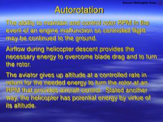
MOTIVATION • For a safe outcome, helicopter autorotation requires precise and time-critical maneuvering in multiple axes. • Consequences of inappropriate timing and magnitude of control inputs can be fatal. • An autorotation trainer that could demonstrate proper control technique would be beneficial for pilot training and safety. • An autorotation trainer should allow pilots to preview and rehearse autorotations from entry conditions throughout the flight envelope. 2005 IHSS, Montreal, Canada
AUTOROTATION SEQUENCE(Entry from Hover) a.) Entry b.) Stabilization c.) Maximum Flare d.) Touchdown. a. b. c. d. 2005 IHSS, Montreal, Canada
THE HUMAN ELEMENT • Humans prefer to operate linear, decoupled systems to nonlinear, coupled systems • Human improvisation to unfamiliar conditions is relatively easy • Human response is: • More repeatable • Less prone to operator noise 2005 IHSS, Montreal, Canada
THE HUMAN ELEMENT • Helicopter dynamics during autorotation are highly nonlinear and coupled • Nonlinear examples: • Lift vs rotor speed • Lift vs airspeed • Coupling examples: • Rotor speed and airspeed both affect lift • Collective affects rotor speed, cyclic both airspeed and rotorspeed • Scanning technique critical for coordinating proper controls sequence • During glide: Airspeed, Nr, ball, radalt • In flare: Nr, pitch, radalt 2005 IHSS, Montreal, Canada
AUTOROTATION:IT’S LIKE HERDING CATS 2005 IHSS, Montreal, Canada
TECHNICAL APPROACH:THE “OPTIMAL PILOT” CONCEPT • Apply optimal control theory to compute optimal trajectories and control inputs required for safe autorotation or one-engine inoperative (OEI) situations – the Optimal Pilot. • The Optimal Pilot will demonstrate autorotation trajectories over a broad range of initial and final conditions and rotorcraft configurations. • Visually integrate and display optimal inputs with the helicopter’s critical states and outside (OTW) view to provide a “sight picture.” • Preview and practice autorotations in a flight simulator using a Flight Director type display to advise the pilot of the optimal control inputs. 2005 IHSS, Montreal, Canada
TECHNICAL APPROACH:OPTIMIZATION METHOD • Two-point boundary value problem – minimize objective (cost) function. • Transformation to parameter optimization problem using Direct-Collocation. • Continuous solution discretized in time using “nodes.” • Rotorcraft equations-of-motion and other non-linear constraints applied at each node. • Parameter optimization problem was solved using a commercially available Sequential Quadratic Programming (SQP) algorithm -- SNOPT • SNOPT is very well suited for near real-time generation of control commands, exhibiting stable and robust behavior for numerous entry conditions and roughly-estimated starting trajectories. 2005 IHSS, Montreal, Canada
TECHNICAL APPROACH:PROBLEM FORMULATION • Cost function includes: • Sink-rate and forward speed at touchdown • Desired touchdown distance or flight time minimization (for OEI situation only) • Weightings on penalty terms were tuned to provide robust solutions across a wide range of autorotation entry conditions. • Longitudinal only, controls were collective and pitch attitude. • Constraints: • Rotorcraft equations-of-motion (represented by non-linear point-mass model). • Rotor speed overspeed and droop limits. • Pitch and collective control limits. • Maximum achievable sink rate. • Maximum pitch rate • Touchdown pitch attitude (to prevent tail strike) 2005 IHSS, Montreal, Canada
TECHNICAL APPROACH:INTEGRATED DISPLAY & FLIGHT DIRECTOR 2005 IHSS, Montreal, Canada
TRAINING METHOD • Compensatory tracking • Compensatory tracking with feedforward cues • Precognitive 2005 IHSS, Montreal, Canada
TESTING & VALIDATION:REAL-TIME IMPLEMENTATION 2005 IHSS, Montreal, Canada
TESTING & VALIDATION:FLIGHT TRAINING DEVICE • Testing performed on a fixed-base FTD by Frasca International. • Wide field-of-view visual display. • High-fidelity cockpit controls and instrument panel. • Simulated helicopter was a Bell-206L-4. • Rotorcraft mathematical model with adequate fidelity for pilot training throughout the flight envelope including autorotation. • FAA approved under 14 CFR Parts 61 and 141. 2005 IHSS, Montreal, Canada
TESTING & VALIDATION:DEVELOPMENT PROCESS • Point-mass model parameters were identified to match the flight simulation model during autorotation. • Primarily scaling of pitch and collective from optimal solution to longitudinal cyclic and collective on the simulator. • Validated using fully-coupled autorotations • A flare law was added to take over from optimal guidance during final flare and landing. • Simple lateral feedback control system was implemented to maintain heading and roll attitude. 2005 IHSS, Montreal, Canada
TESTING & VALIDATION:EVALUATION METHOD • Optimizer continuously updates optimal solution based on rotorcraft states obtained from simulator. • Update is stopped when engine is failed. • Procedure: • Fly to required entry condition. • Stabilize and wait for a stable optimal solution. • Fail engine and enter automated autorotation. • Autorotation trajectory flown is based on the solution just prior to engine failure. • Safe or crash landing determined by the FTD simulation model. 2005 IHSS, Montreal, Canada
TESTING & VALIDATION:EVALUATED ENTRY CONDITIONS 2005 IHSS, Montreal, Canada
TESTING & VALIDATION:FULLY-COUPLED AUTOROTATIONS(400 Ft and 100 Ft Hover Entry) 2005 IHSS, Montreal, Canada
TESTING & VALIDATION:CONCLUSIONS • Optimal pilot concept was validated on the Frasca FTD. • Optimal guidance allowed safe autorotation from well within the “avoid” regions of the Height-Velocity envelope. • Ability to train a pilot on autorotation technique using the flight director display was also demonstrated (results presented at AHS Forum 61, Grapevine, TX). • Incorporate Optimal Pilot concept in a CBT to allow pilots to preview autorotations. 2005 IHSS, Montreal, Canada
COMPUTER BASED AUTOROTATION TRAINER:EXAMPLE AUTOROTATIONS • Autorotations flown by the optimal pilot (optimal commands are coupled to rotorcraft controls). • Show “extreme” entry conditions to illustrate the effectiveness of the concept. • Time history data: altitude (H, ft), airspeed (V, kts), pitch attitude (, degrees), vertical velocity (w, fpm), rotor speed (, %), collective (c, %). • Bell 206 Model; Power failure at time = 0. • Video clips show OTW sight picture and optimal pitch attitude/collective commands. 2005 IHSS, Montreal, Canada
AUTOROTATION CBT:CONTROL INPUT PREVIEW • Example cueing display for an autorotation from a 200ft hover entry • Pitch attitude preview on right, collective on left. • Tick marks show 1 second time intervals. • Pitch attitude cue indicates immediate pitch down followed by a steep pitch up with a final nose-over to avoid tail strike. • Collective cueing indicates immediate lowering of collective with collective pull at the end of the maneuver. 2005 IHSS, Montreal, Canada
EXAMPLE AUTOROTATIONS:ENTRY CONDITIONS • H-V flight envelope shows “avoid” regions for Bell 206L-4. • Example autorotations shown for: • Heavy weight (4500 lbs), 400 ft hover entry (within avoid region). • Heavy weight (4500 lbs), 80 ft/60 kts entry (knee point of avoid region). • Medium weight (3600 lbs), 200 ft hover entry (within avoid region). • Medium weight (3600 lbs), 20 ft/40 kts entry (outside avoid region). 2005 IHSS, Montreal, Canada
EXAMPLE AUTOROTATION TIME HISTORY(HEAVY WEIGHT, 400 FT HOVER ENTRY)(Touchdown: 18 kts, 248 fpm) 2005 IHSS, Montreal, Canada
EXAMPLE AUTOROTATION VIDEO(HEAVY WEIGHT, 400 FT HOVER ENTRY)(Touchdown: 18 kts, 248 fpm) 2005 IHSS, Montreal, Canada
EXAMPLE AUTOROTATION TIME HISTORY(HEAVY WEIGHT, 80 FT/60 KT ENTRY)(Touchdown: 19 kts, 221 fpm) 2005 IHSS, Montreal, Canada
EXAMPLE AUTOROTATION VIDEO(HEAVY WEIGHT, 80FT/60KT ENTRY)(Touchdown: 19 kts, 221 fpm) 2005 IHSS, Montreal, Canada
EXAMPLE AUTOROTATION TIME HISTORY(MEDIUM WEIGHT, 200 FT HOVER ENTRY)(Touchdown: 20 kts, 369 fpm) 2005 IHSS, Montreal, Canada
EXAMPLE AUTOROTATION VIDEO(MEDIUM WEIGHT, 200 FT HOVER ENTRY)(Touchdown: 20 kts, 369 fpm) 2005 IHSS, Montreal, Canada
EXAMPLE AUTOROTATION TIME HISTORY(MEDIUM WEIGHT, 20FT/40KT ENTRY)(Touchdown: 20 kts, 211 fpm) 2005 IHSS, Montreal, Canada
EXAMPLE AUTOROTATION VIDEO(MEDIUM WEIGHT, 20FT/40KT ENTRY)(Touchdown: 20 kts, 211 fpm) 2005 IHSS, Montreal, Canada
AUTOROTATION CBT CONCEPT • Objectives: • Provide pilots with a preview of the control inputs and trajectory required for safe autorotation from entry conditions across the flight envelope. • Provide pilots with an OTW sight picture of the autorotation. • Allow pilots to rehearse autorotations in an interactive environment. • CBT configuration: • Preset rotorcraft model parameters (for specific rotorcraft) or allow user to setup the rotorcraft model. • User sets up entry flight condition (speed, altitude, weight, wind, etc). • Allow user to adjust cost and constraint parameters (allowable rotor droop, for example)? • CBT Output: • OTW scene with or without superimposed optimal trajectory information. • Other external views to demonstrate trajectory and rotorcraft state information • Time history information 2005 IHSS, Montreal, Canada
AUTOROTATION CBT:NEXT STEPS • Evaluate Industry interest and required functionality and features for: • PC based CBT (preview autorotations on the desktop). • PC based flight simulation training aid (provide cueing during flight simulation). • Refine optimal pilot algorithm: • Automatic point mass parameter estimation • Winds • Develop a graphical user interface. • Validate further using high-fidelity moving-base flight simulator. 2005 IHSS, Montreal, Canada