Download
1 / 39
390 likes | 517 Vues
Imaging the event horizon of Sgr A* A VLBI processor for the SMA. Jonathan Weintroub Submillimeter Array Project Harvard-Smithsonian Center for Astrophysics CfA collaborators on IR&D VLBI Processor Proposal: Jim Moran, Bob Wilson, Lincoln Greenhill, Mark Reid, John Test

E N D
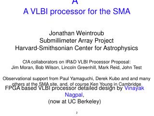
Imaging the event horizon of Sgr A* A VLBI processor for the SMA Jonathan Weintroub Submillimeter Array Project Harvard-Smithsonian Center for Astrophysics CfA collaborators on IR&D VLBI Processor Proposal: Jim Moran, Bob Wilson, Lincoln Greenhill, Mark Reid, John Test Observational support from Paul Yamaguchi, Derek Kubo and and many others at the SMA site, and, of course Ken Young in Cambridge FPGA based VLBI processor detailed design by Vinayak Nagpal, (now at UC Berkeley) 2
Other Collaborators • MIT-Haystack (Doeleman, Whitney, Rogers, Corey) • UC Berkeley/BWRC/CASPER (Werthimer, Wright, ...) • CARMA (Plambeck) • CSO (Chamberlin) • JCMT (Tilanus, Friberg) • SMTO (Freund) • CfA Maser Lab (Vessot, Phillips, Mattison) 3
Evidence for a super massive black hole (SMBH) in in Sgr A* • Widely accepted that most galaxies have SMBHs at their centers • Closest candidate is Sgr A* at the galactic center • Measurements have been made of the orbits of a number of stars bound to Sgr A* with periods as short as 15 years at Keck and VLT using adaptive optics (Genzel et al., 2003, Ghez et al. 2005.) • These show the central mass to be about 3.9x10⁶ MΘ • The mass density must be greater than 1022 MΘ pc-3 because lack of proper motion of Sgr A* means > 10% of the mass must be tied to Sgr A* (Reid and Brunthaler, 2004), which has size < 1AU . • Most likely explanation: mass is in the form of a SMBH • Schwarzschild radius is about 1.2x1012 cm or 10 μas 5
Observed (and projected) orbits of stars bound to Sgr A* 1995 - 2010 This animation was created by Prof. Andrea Ghez and her research team at UCLA and is from data sets obtained with the W. M. Keck Telescopes. 7
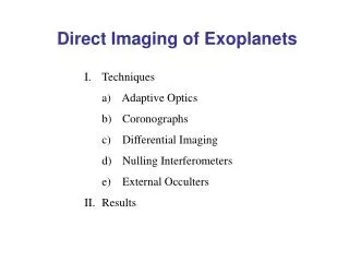
Submillimeter VLBI is uniquely suited • Angular resolution is as fine as 20 μas (λ=0.8 mm on global baselines ~5000 km), several factors better than any other available technique in any waveband. • Thus can resolve and image the structure of emission at the event horizon. • The galactic center becomes optically thin at λ~1 mm. • At longer wavelengths, the image is blurred by the turbulence of ionized gas (scattering ∝ λ2) • In the optical Sgr A* is obscured by dust. • In optical and infra 8
What might we see? • The image of synchrotron radiation from gas in the accretion disk is highly distorted due to strong field effects of GR. • The image consists of a ring of emission and a central “shadow”. • Theoretical predictions suggest the diameter of the distorted image should be of the order of 50μas. • The detailed characteristics depend on the spin of the black hole, as well as the opacity and distribution of the emitting gas. • A number of theoretical predictions are in the literature. 11
Static modelFalcke et al. ApJ 528,L13 (2000) ←Maximally rotating SMBH, with envelope of radiating gas in free-fall ←Non rotating SMBH, medium has uniform emissivity from Keplerian shells ↑ Simulated “actual” intensity ↑ observation λ=0.6 mm ↑ observation λ=1.3 mm Horizontal axis in these simulations is in units of the gravitational radius, about 5 μas. 12
Dynamic model Simulation of a compact emission region in a circular orbit around a spinning black hole. This is the low spin example. Broderick and Loeb MNRAS(2005) 13
high spin animation: Effect of spin is detectable in a 20 μas observation. Broderick and Loeb MNRAS(2005) 14
The observed angular size of Sgr A* vs wavelength • The source is elliptical;two solid lines indicate major and minor axes • Shows λ2 dependence characteristic of plasma scattering • Data points at 1.5 mm and 6 mm indicate the true source size in the range 50 - 100 μas • At longer wavelengths, angular size is dominated by interstellar scattering in the ionized plasma of the inner galaxy. Doeleman et al. AJ 121, 2610 (2001) 15
Submillimeter Valley, Mauna Kea, HI JCMT 15 m single dish CSO 10 m single dish SMA eight 6 m dishes (shown in the compact configuration) 16
Features of an SMA VLBI processor • Coherently sum the signals from the SMA antennas, and the CSO and JCMT • Compensate delays (geometric, atmospheric and systematic) • Compensate phase (“stop the fringes”) • Format the data for bulk data storage (for Mark5b processor, from MIT/Haystack), up to 4 Gb/s • Do this all with maser controlled time stability • Do it cheaply, quickly, and with minimal impact on connected SMA operations 19
Maser time standard • Maser references all local oscillators in the system, and the sampling clock. • Stability requirements are most stringent in respect of the sky LO, at around 230 GHz or 345 GHz, a few parts in 1014 needed on 10 s time scales. • Absolute time at stations controlled by locking a maser locked 1pps to GPS. Residual error delay removed by post correlation fringe search. • Masers meeting all of these requirements, especially at a budget, are rare beasts 22
Allan Deviation for Selected Hydrogen maser time standards • P2 maser now at SMA on Mauna Kea • P8 maser at SMTO on Mount Graham 24
Design of a proof of concept VLBI processor • Tap off signals from SMA antennas in the IF • Provide custom downconversion and anti-alias filters • Sample over wide band block • Provide the phased array summer and VLBI processor in FPGA • Need a strategy for delay calibration 25
Phased array I τ ϕ τ Simple case, delay compensates perfectly (in principle). Requires optical delay elements. τ 34
Phased Array 2 τ ϕ τ Heterodyne introduces a fixed phase offset across the entire band f τ LO LO mix mix ϕ2 ϕ1 ϕ ϕ1-ϕ2 35
Phased Array 3 • The way it is actually done. • Heterodyne introduces a fixed phase as before • Position of delay after mix results in phase rotation τ ϕ τ LO mix mix LO ϕ1 ϕ2 ϕ τ ϕ1-ϕ2 f 36
Frequency plan SMA first downconverter output Amp Custom block filters Amp 0.528 1.008 f 1.280 f 0.5 GHz 1.5 GHz 0.768 1.520 1 GHz 1.040 Amp Amp 1024 MHz 1024 MHz 37 f f
iBOB and iADC schematic phased array 8 Gb/s per antenna (or per summed set) ant1 ant2 8 Gb/s ant3 ant4 iBOB 1 ant5 8 Gb/s ant6 VSI ant7 iBOB 3 ant8 iBOB 2 Mark5b+ 38
Time domain vs Frequency domain delay τ1 ↓ f: complex, albeit that phase adjustment is naturally integrated. delay τ2 delay τ3 ϕ1(k) adjust FFT N ϕ2(k) adjust delay τn FFT N ↑ t: simple, but less flexible (in particular phase adjustment difficult) ϕ3(k) adjust FFT N ϕn(k) adjust FFT N 39
Selected time domain(three vernier stages of delay) • First stage, coarse delay • Precise to 4 ns • Max delay 4 μs • Delay ↑ 4 samples repeat • Delay ↓ 4 samples skipped • Control via PowerPC (PPC) 40
Fine delay Barrel shifter picks one of four concatenated samples for 1 ns delay precision. 41
Super-fine delay • Digital FIR filter fine tunes the delay (uniform amplitude response) • D can be fractional to set a delay for a fraction of a sample period. • Pre-compute coefficients for 0.1 ns delay precision to implement a 10-tap FIR approximation to the delay filter. 42
Super-fine delay • Digital FIR filter fine tunes the delay (uniform amplitude response) • D can be fractional to set a delay for a fraction of a sample period. • Pre-compute coefficients for 0.1 ns delay precision to implement a 10-tap FIR approximation to the delay filter. 43
Super-fine delay • Demux-by-four makes this element rather complex. • number of taps=number of stages, but . . . • four multiplications and four partial sums generated per stage. • combine the partials according to the lower diagram (another exercise left to the reader) 44
Bench test of delay block1.024 GSa/s ←antenna 1 ←antenna 2 ←incoherent sum 45
Bench test of delay blocklook for peak of cross-correlation to calibrate delay 46
Bench test of delay blockcorrect delay programed ←antenna 1 ←antenna 2 ←coherent sum 47
Bench test of delay blockcross-correlation with calibrated delay 48
The calibration probemHow do we determine the correct delays? • We know the array geometry fairly well from SMA and eSMA baselines (though may not be sufficiently precise for 500 MHz band.) • Dynamic tracking of the atmospheric contribution is needed--consider using the existing SMA correlator running in parallel • System contributions (cables, analog IF elements, etc, not in the SMA correlator path) are unknown, though only need to be measured once. • After some consideration decided to design a iBOB based correlator based on existing CASPER library element. 49
iBOB Correlator • Single baseline to fit within one iBOB • Time multiplex seven measurements delay to reference antenna. • Needs to run at full speed 1024 MSa/s with 4-fold demux • Turned out to be quite a complex design, and time sink. • Dynamic range still a problem. 50
iBOB Correlator bench tests Autocorrelation SNR -2 dB • Band-limited noise input • Noise has correlated and un-correlated component • Ratio corr/uncorr is SNR • Slope of phase response is delay 51
Correlator response with poorer SNR ←SNR -9 dB ←SNR -12 dB ←SNR -15 dB \ 52
Fringe stopping • Analog approach needed in time domain processor • SMA SIS LO has DDS controlled phase rotation • Second heterodyne in system requires a secondary phase rotation • Plan to phase rotate the 1024 MHz sampler clock (an implicit heterodyne to baseband) on 7 antennas with respect to the reference antenna, box to do this currently being designed (using quadrature modulators mass produced for mobile phone industry) • Was the time domain approach the correct decision? 54
Conclusions and future work • VLBI imaging of the SMBH in Sgr A* represents a unique and challenging opportunity • Proof of concept design shows feasibility of a budget phased array processor for the eSMA • Work needed particularly in the area of calibration and correlator dynamic range • We have just attempted 230 GHz VLBI on Sgr A* (JCMT on Mauna Kea, with reference distribution and data collection at SMA). Other stations are SMTO in Arizona, and a single 10 m CARMA dish. Primitive imaging could measure size and ellipticity of Sgr A* • Maser time standards, availability and performance are concerns 56