3F4 Line Coding
3F4 Line Coding. Dr. I. J. Wassell. Introduction. Line coding is the procedure used to convert an incoming bit stream, b k to symbols a k which are then sent as pulses a k h T (t-kT) on to the channel The line coding technique affect the properties of the transmitted signal

3F4 Line Coding
E N D
Presentation Transcript
3F4 Line Coding Dr. I. J. Wassell
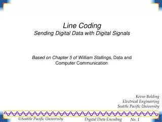
Introduction • Line coding is the procedure used to convert an incoming bit stream, bk to symbols ak which are then sent as pulses akhT(t-kT) on to the channel • The line coding technique affect the properties of the transmitted signal • Desirable properties are • Self Synchronisation. There should be sufficient information in the transitions and zero-crossings to permit symbol timing clock regeneration
Introduction • Spectrum suited to the channel. The PSD of the transmitted signal should be compatible with the channel frequency response Hc(w), eg, • Many channels cannot pass dc (zero frequency) owing to ac coupling • Lowpass response limits the ability to carry high frequencies
Line Codes for Copper Cables • Following a qualitative introduction to some practical line codes, we will look at a framework for their quantitative analysis • Unipolar Binary • binary symbols transmitted • pulse weightings, ak=0 or A Volts, eg, ‘0’ and ‘1’ • no guarantee of transitions (for timing regeneration) • transmitted signal has non-zero mean, so the channel must be able to pass dc. If not, errors will occur with long runs of ‘1’s in the data
1 0 1 1 0 0 0 0 1 1 0 1 Unipolar Binary A 0
Line Codes for Copper Cables • Polar Binary (do not confuse with bipolar) • binary symbols transmitted • pulse weightings, ak=-A or A Volts, eg, ‘0’ and ‘1’ • no guarantee of transitions (for timing regeneration) • transmitted signal is zero mean (provided data is equiprobable), but there is still a high PSD at low frequencies, therefore still a problem with channels which do not pass dc
1 0 1 1 0 0 0 0 1 1 0 1 Polar Binary A 0 -A
Line Codes for Copper Cables • Bipolar (or Alternate Mark Inversion (AMI)) • ternary (3 level) symbols transmitted • pulse weightings, ak=0 or either -A or +A Volts, eg, ‘0’ or ‘1’, that is, • ‘0’ sent as ak=0 • ‘1’ sent as ak=-A or +A alternately • no guarantee of transitions (for timing regeneration) • signal mean is always zero (independent of data) • Spectral null at dc means there is no longer a problem if channel does not pass dc • 1 binary symbol sent as 1 ternary symbol, 1B1T code
1 0 1 1 0 0 0 0 1 1 0 1 A 0 -A Bipolar (AMI)
Line Codes for Copper Cables • High Density Bipolar (HDBn) • modified bipolar codes which guarantee transitions despite runs of zeros. • thus substitute runs of more than n zeros • an alternative name is BnZS • in this case substitute runs of n or more zeros • HDB3 is a popular code • note HDB3 is equivalent to B4ZS
HDB3 • Any run of 4 zeros is replaced by the special pattern: B00D • D is sent as +/- A, such that successive D’s have alternating polarity (1st D is arbitrary) • B is sent as 0 or +/- A. Select B such that the next D violates the AMI alternating polarity result, ie send B as 0 if D violates the polarity rule. Otherwise send B=D to force a violation of the alternating polarity rule
HDB3 • Equivalently, • B is sent as 0 if there has been an odd number of input ‘1’s since the last special sequence B00D • B is sent as +/- A if there has been an even number of input ‘1’s since the last special sequence B00D • All other symbols obey the AMI rules • The scheme allows the unique detection of the special sequences, since polarity violations correspond with the D symbols. • An overall mean of zero is achieved
1 0 1 1 0 0 0 0 1 1 0 1 A 0 -A HDB3
HDB3 • There are never more than 3 consecutive zeros, so plenty of edges for timing regeneration • The channel is not required to pass dc • The transmit power requirement is a little greater than AMI (about 10%)
Power Spectra for Line Codes • We can use the earlier results concerning power spectra to derive the PSD for PAM schemes • Initially we will consider the case where the symbols are transmitted as weighted impulses. • We will then generalise to arbitrary pulse shapes
Signal TX as impulse train • A PAM signal sent as a weighted impulse train is, Where Ts is the symbol period. We will show that the PSD of x(t) is given by, and Which is the discrete Autocorrelation function (ACF). Also note that R(m) = R(-m) for real valued an
Proof • Using direct method, ie, • The truncated signal xT(t) is, • Now, And substituting for xT(t) gives,
Proof Now,
Proof • Now,
Proof • Let, • Replace the outer sum over index n by 2N+1,
Proof • Now, Where T=(2N+1)Ts, so
Proof Remembering that R(m) = R(-m) for real valued an
Proof • Note that for R(m)=0 for all m except zero, the PSD reduces to e.g., for polar binary line coding.
For Arbitrary Pulse Shapes • Recall that a PAM signal with a desired pulse shape h(t) may be generated by filtering (actually convolving) the weighted impulse train with a filter whose impulse response is h(t) • From the power spectra results we obtain,
PSD of Specific Schemes • Given a particular line coding scheme which generates symbols ak, the transmitted PSD is calculated as follows: • Determine the discrete ACF Where, • M is the number of possible values that akak+m can take on • Ri is the ith value of akak+m • pi is the probability that Ri occurs
PSD of Specific Schemes • Evaluate impulse train PSD • Substitute R(m) into the PSD formula, • Evaluate PSD with pulse shaping • Multiply Sx(w) by |H(w)|2,
Example- Polar Binary • So,
a 0 t -b/2 b/2 Example- Polar Binary • Now extend to pulses with a rectangular shape and duration Ts. To do this we convolve the impulse stream with a filter h(t) with a rectangular impulse response, i.e., from the E and I Data Book, h(t) FT
Example- Polar Binary • In our example, b=Ts and a=1, so the filter frequency response is, This response has an amplitude of Ts at w = 0 and zero crossings at multiples of 2p/Ts rad/s or 1/Ts Hz.
Example- Polar Binary • Now the PSD at the output of the filter H(w) is, This response has an amplitude of Ts at w = 0 and zero crossings at multiples of 2p/Ts rad/s or 1/Ts Hz. This is consistent with the PSD plot for polar binary signalling with rectangular pulses.
Example- Polar Binary PSD*Ts PSD*Ts f *Ts f *Ts Impulse Train PSD Rectangular Pulse PSD
Example- Bipolar (AMI) • So,
Example- Bipolar (AMI) • Note that if rectangular pulses are employed as in the previous Polar example, the resulting PSD is given by, Where, Note the zero crossings at multiples of 2p/Ts rad/s or 1/Ts Hz and the lowering of the frequency sidelobes evident in the PSD plot.
Example- Bipolar (AMI) PSD*Ts PSD*Ts f *Ts f *Ts Impulse Train PSD Rectangular Pulse PSD
ACF With Non-Zero Mean Data • Sometimes the line coded data will have a non-zero mean value. • This could be due to • The line coding scheme, e.g., unipolar • The probability distribution of the data • Incorrect signalling voltages owing to faults • The result is that the R(m) will have finite values for m in the range +/- infinity
ACF With Non-Zero Mean Data • The result for Sx(w) is valid but is hard to interpret physically • The solution is to express R(m) as the sum of two parts • The first part has a constant value of R over the range of m from + to - infinity • The second part has non-zero values of R over a finite range of m
ACF With Non-Zero Mean Data • The advantage of this approach is that the first term can be represented in a format that is consistent with physical observations. • We will now show that this representation comprises a sequence of spikes (impulses) in the frequency domain, occurring at multiples of the bit rate.
ACF With Non-Zero Mean Data • Suppose that R(m)=R for all m, then we can express the PSD as follows • Note the similarity in form to the Fourier series representation of an impulse train, Note in time domain
ACF With Non-Zero Mean Data • Reminder, the Fourier Series (FS) for a periodic function is, i.e., a weighted (complex) sum of phasors. • We now wish to find the FS of the rectangular pulse train x(t), t x(t) A 0 t To
ACF With Non-Zero Mean Data • Now the coefficients are given by, For the case where t goes to zero and At = 1 (i.e., a unit impulse train),
ACF With Non-Zero Mean Data • So we know, Remembering that ck=1/T0 when x(t) is a sequence of unit impulses we can write,
ACF With Non-Zero Mean Data • If we substitute, w=t,m=k and T0=2p/Ts, to get the equivalent relation in the frequency domain, And hence we may express Sx(w) as a series of impulses in the frequency domain,
ACF With Non-Zero Mean Data • The PSD due to a constant R for all m consists of spikes, known as line spectral components, at multiples of wo=2p/Ts • This result enables simplified calculation of PSDs when R(i) can be written in the form, First calculate the PSD for R(i)=C(i), then add on the line spectrum for R(i)=R
Example- Unipolar Binary • So, The second term is known as a line spectrum
Example- Unipolar Binary PSD*Ts PSD*Ts f *Ts f *Ts Impulse Train PSD Rectangular Pulse PSD
Scrambling • Some components of a transmission system work better if the bit sequence bk is random, ie, independent and uncorrelated • Timing regeneration not possible with some line codes if long sequences of ‘0’s or ‘1’s occur • Equalisers (see next section) rely on random bit sequences for successful operation • A common solution is to randomise (or scramble) the input bit sequences (in a known manner) prior to line coding
Scrambling • The received signals then appear as if they come from a random source • Unscrambling after detection restores the correct bit sequence • A simple way to generate scramblers is to XOR the data with the output of a feedback shift register arrangement.