FSM Word Problems
FSM Word Problems. Notes: Review for Test #2 – Monday Studio #8: Reading assignment is required & due next week Today: First Hour : Finite string recognizer, Complex counter Section 8.5 of Katz’s Textbook In-class Activity #1

FSM Word Problems
E N D
Presentation Transcript
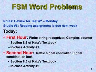
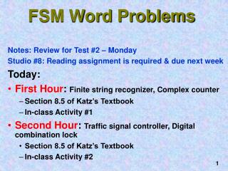
FSM Word Problems • Notes: Review for Test #2 – Monday • Studio #8: Reading assignment is required & due next week • Today: • First Hour: Finite string recognizer, Complex counter • Section 8.5 of Katz’s Textbook • In-class Activity #1 • Second Hour: Traffic signal controller, Digital combination lock • Section 8.5 of Katz’s Textbook • In-class Activity #2
Katz Material not Covered CoCO doesn't cover everything in Katz. Omitted material includes: ASM charts The ABEL language all of Chapter 9 is skipped
One of the most difficult problems is making an imprecise description of a finite state machine into a precise one. Have you covered all the states? Omissions can cause failures, crashes, death and destruction, etc. This is the Hardware equivalent of a Software programming error. Word Problems
One input: X One output: Z Description: Z is 1 if the 3 previous input bits are 010, and 100 has never been seen. Unstated assumptions: RESET starts the FSM at the "reset" state Z is asserted when the following bit is seen.A Moore Machine implementation. Finite String Recognizer Serial Finite State Machine
X: 0 0 1 0 1 0 1 0 0 1 0 Z: - 0 0 0 1 0 1 0 1 0 0 0 Example Serial Behavior • Z is 0 even though the three previous inputs are 010, because 100 was seen earlier.
Formal Design State Transition Diagram Reset S0 • Create sequences of states for the strings that the machine recognizes: 010 and 100. • Note we reset to S0. • Consider the unlabelled transitions. [0] 1 0 S4 S1 [0] [0] 1 0 S2 S5 [0] [0] 0 0 0,1 S3 S6 [1] [0]
State S3 Diagram Development Reset S0 [0] 1 0 • Where do we go from S3? • A 1 means the last 3 bits are 101, so go to S2. • A 0 means we’ve seen 100, so go to S6. S4 S1 [0] [0] 1 0 S2 S5 01? [0] [0] 1 0 0 0,1 0 S3 S6 010 [1] [0] 100
States S1 and S4 Diagram Development Reset S0 • Loop in S1 until we see our first 1. • Loop in S4 until we see our first 0. [0] 0 1 0 1 1? S4 S1 [0] [0] 0? 1 0 S2 S5 01? [0] [0] 0 0 0,1 1 0 S3 S6 010 [1] [0] 100
Reset S0 [0] 0 1 0 1 S4 1? S1 [0] [0] 1 0? 1 0 1 S2 S5 01? [0] [0] 10? 1 0 0 0 S3 S6 0,1 [1] [0] 010 100 States S2 and S5 Diagram Development • S2 means the last 2 bits are 01, which may be a prefix of 010. • If the next bit is 1, the last 2 bits are now 11, maybe a prefix of 100. That’s S4. • S5: Last 2 bits are 10. If next bit is 1, maybe that’s a prefix for 010. Go to S2.
Write sample inputs and outputs to understand it. Write sequences of states and transitions for the strings that the FSM is to recognize. Add missing transitions, using existing states when possible. Verify that the state diagram matches the FSM. Review of Design Steps Katz's Method
Design a 3-bit counter, with one input bit, a mode, M. If M = 0, step to the next binary number in the sequence 000, 001, 010, 011, 100, 101, 110, 111, … If M = 1, step to the next Gray code number in the sequence 000, 001, 011, 010, 110, 111, 101, 100, ... Complex Counter
Note that we can switch modes at any time. Mode Input M 0 0 1 1 1 0 0 Current State 0 0 0 0 0 1 0 1 0 1 1 0 1 1 1 1 0 1 1 1 0 Next State (Z2 Z1 Z0) 0 0 1 0 1 0 1 1 0 1 1 1 1 0 1 1 1 0 1 1 1 Try Some Sample Inputs
Reset S0 [000] 1 0 1 S1 [001] 1 0 S2 1 [010] 0 1 S3 [011] 0 1 S4 [100] 1 0 S5 [101] 0 S6 [110] 1 0 1 0 S7 [111] Formal Representation • One state for each output combination • Add appropriate arcs for the mode control
Reset S0 [000] 1 0 1 S1 [001] 1 0 S2 1 [010] 0 1 S3 [011] 0 1 S4 [100] 1 0 S5 [101] 0 S6 [110] 1 0 1 0 S7 [111] Do Activity #1 Now Reset S0 [0] 0 1 0 1 S4 1? S1 [0] [0] 1 0? 1 0 1 S2 S5 01? [0] [0] 10? 1 0 0 0 S3 S6 0,1 [1] [0] 010 100 FSM String Recognizer, Z=1 if 010 is seen, but 100 not seen before Complex Counter
Farmroad C HL FL Highway Highway FL HL C Farmroad Diagram of Intersection
A busy highway is intersected by a little-used farm road. Detectors C sense the presence of cars waiting on the farm road. With no car is on farm road, the lights remain Green in the highway direction. If vehicle is on the farm road, highway lights go from Green to Yellow to Red, allowing the farm road lights to become Green. These stay Green only as long as a farm road car is detected but never longer than a set time interval. When these are met, farm lights transition from Green to Yellow to Red, allowing highway to return to Green. Even if farm road vehicles are waiting, the highway gets at least a set interval as Green. Traffic Light Controller
Assume you have an interval timer that generates a short time pulse (TS) and a long time pulse (TL) in response to a start timer (ST) signal. TS is to be used for timing Yellow lights and TL for Green lights Available Timers
Input Signal reset C TS TL Output Signal HG, HY, HR FG, FY, FR ST Description place FSM in initial state detect vehicle on farm road short time interval expired long time interval expired Description assert green/yellow/red highway lights assert green/yellow/red farm road lights start timing a short or long interval Tabulate Inputs & Outputs
Some light configurations imply others. State S0 S1 S2 S3 Description Highway green (farmroad red) Highway yellow (farmroad red) Farmroad green (highway red) Farmroad yellow (highway red) Tabulate Unique States
Reset places timer in S0, highway green and farm road red. Reset also starts the timer. Stay in S0 as long as no one is on the farm road. Even if there is a farm road vehicle, the highway stays green at least long as the long time interval. (Unstated in Katz) There will never be a bicycle or pedestrian on the farm road. List Assumptions
Traffic Signal State Diagram TL + C Reset S0: HG S1: HY S2: FG S3: FY S0 TL•C/ST S1 S3 TL: long time interval expired S2 C: detect vehicle on farmroad
Traffic Signal State Diagram TL + C Reset S0: HG S1: HY S2: FG S3: FY S0 TL•C/ST TS S1 S3 TS/ST TS: short time interval expired S2 ST: start timing a short or long interval
Traffic Signal State Diagram TL + C Reset S0: HG S1: HY S2: FG S3: FY S0 TL•C/ST TS S1 S3 TS/ST TL + C/ST S2 TL: long time interval expired C: detect vehicle on farm road TL • C ST: start timing a short or long interval
Traffic Signal State Diagram TL + C Reset S0: HG S1: HY S2: FG S3: FY S0 TL•C/ST TS/ST TS S1 S3 TS TS/ST TL + C/ST S2 TS: short time interval expired ST: start timing a short or long interval TL • C
3 bit serial lock controls entry to locked room. Inputs are RESET, ENTER, 2 position switch for bit of KEY data. Locks generates an UNLOCK signal when KEY matches internal combination. ERROR light illuminated if KEY does not match combination. Sequence is: (1) Press ENTER, (2) enter KEYbit, (3) Press ENTER, (4) repeat (2) & (3) two more times. In the last round, it is not necessary to press ENTER. Combination Lock
Problem specification is incomplete: how do you set the internal combination? exactly when is the ERROR light asserted? Incomplete Specification
Make reasonable assumptions, decide whether combination is hardwired into logic or stored in a register? error is asserted as soon as an error is detected or waits until the full combination has been entered? Our design: combination is stored in a register and error is asserted after the full combination has been entered Make Assumptions Why is it just possibly a bad idea to indicate an error immediately on seeing the first bad bit ?
Block Diagram of Lock Operator Data Internal Combination Inputs: Reset, Enter, Key-In, L0, L1, L2 Outputs: Unlock, Error
What sequences lead to opening the door? Do error conditions on a second pass … Enumerate the States
State Diagram of Lock Enter Enter Comp1 Error1 KI L1 KI = L1 Enter Enter Idle1 Idle1' Reset + Enter Reset Enter Enter Start Comp2 Error2 Reset • Enter KI L2 KI = L2 Comp0 Reset Reset Error3 KI = L0 KI L0 Done [Error] [Unlock] Enter Enter Reset Idle0 Idle0' Reset Start Start
Do Activity #2 Now • Due: End of Class Today. • RETAIN THE LAST PAGE(S) (#3 onwards)!! • For Next Class: • Bring Randy Katz Textbook, & TTL Data Book • Required Reading: • Sec 11.1-11.3, skim 11.2 of Katz, omit the ABEL and ASM descriptions • This reading is necessary for getting points in the Studio Activity!