Lucas-Kanade Motion Estimation
Lucas-Kanade Motion Estimation. Thanks to Steve Seitz, Simon Baker, Takeo Kanade, and anyone else who helped develop these slides. Why estimate motion?. We live in a 4-D world Wide applications Object Tracking Camera Stabilization Image Mosaics 3D Shape Reconstruction (SFM)


Lucas-Kanade Motion Estimation
E N D
Presentation Transcript
Lucas-Kanade Motion Estimation Thanks to Steve Seitz, Simon Baker, Takeo Kanade, and anyone else who helped develop these slides.
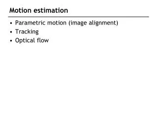
Why estimate motion? • We live in a 4-D world • Wide applications • Object Tracking • Camera Stabilization • Image Mosaics • 3D Shape Reconstruction (SFM) • Special Effects (Match Move)
Key assumptions • color constancy: a point in H looks the same in I • For grayscale images, this is brightness constancy • small motion: points do not move very far • This is called the optical flow problem Problem definition: optical flow • How to estimate pixel motion from image H to image I? • Solve pixel correspondence problem • given a pixel in H, look for nearby pixels of the same color in I
Optical flow constraints (grayscale images) • Let’s look at these constraints more closely • brightness constancy: Q: what’s the equation? H(x, y) = I(x+u, y+v) • small motion: (u and v are less than 1 pixel) • suppose we take the Taylor series expansion of I:
Optical flow equation • Combining these two equations The x-component of the gradient vector. What is It ? The time derivative of the image at (x,y) How do we calculate it?
Optical flow equation • Q: how many unknowns and equations per pixel? 1 equation, but 2 unknowns (u and v) • Intuitively, what does this constraint mean? • The component of the flow in the gradient direction is determined • The component of the flow parallel to an edge is unknown
Solving the aperture problem • Basic idea: assume motion field is smooth • Lukas & Kanade: assume locally constant motion • pretend the pixel’s neighbors have the same (u,v) • If we use a 5x5 window, that gives us 25 equations per pixel! • Many other methods exist. Here’s an overview: • Barron, J.L., Fleet, D.J., and Beauchemin, S, Performance of optical flow techniques, International Journal of Computer Vision, 12(1):43-77, 1994.
Lukas-Kanade flow • How to get more equations for a pixel? • Basic idea: impose additional constraints • most common is to assume that the flow field is smooth locally • one method: pretend the pixel’s neighbors have the same (u,v) • If we use a 5x5 window, that gives us 25 equations per pixel!
RGB version • How to get more equations for a pixel? • Basic idea: impose additional constraints • most common is to assume that the flow field is smooth locally • one method: pretend the pixel’s neighbors have the same (u,v) • If we use a 5x5 window, that gives us 25*3 equations per pixel!
Solution: solve least squares problem • minimum least squares solution given by solution (in d) of: • The summations are over all pixels in the K x K window • This technique was first proposed by Lukas & Kanade (1981) Lukas-Kanade flow • Prob: we have more equations than unknowns
Conditions for solvability • Optimal (u, v) satisfies Lucas-Kanade equation • When is This Solvable? • ATA should be invertible • ATA should not be too small due to noise • eigenvalues l1 and l2 of ATA should not be too small • ATA should be well-conditioned • l1/ l2 should not be too large (l1 = larger eigenvalue)
Edges cause problems • large gradients, all the same • large l1, small l2
Low texture regions don’t work • gradients have small magnitude • small l1, small l2
High textured region work best • gradients are different, large magnitudes • large l1, large l2
Errors in Lukas-Kanade • What are the potential causes of errors in this procedure? • Suppose ATA is easily invertible • Suppose there is not much noise in the image • When our assumptions are violated • Brightness constancy is not satisfied • The motion is not small • A point does not move like its neighbors • window size is too large • what is the ideal window size?
Revisiting the small motion assumption • Is this motion small enough? • Probably not—it’s much larger than one pixel (2nd order terms dominate) • How might we solve this problem?
u=1.25 pixels u=2.5 pixels u=5 pixels u=10 pixels image H image I image H image I Gaussian pyramid of image H Gaussian pyramid of image I Coarse-to-fine optical flow estimation
warp & upsample run iterative L-K . . . image J image I image H image I Gaussian pyramid of image H Gaussian pyramid of image I Coarse-to-fine optical flow estimation run iterative L-K
A Few Details • Top Level • Apply L-K to get a flow field representing the flow from the first frame to the second frame. • Apply this flow field to warp the first frame toward the second frame. • Rerun L-K on the new warped image to get a flow field from it to the second frame. • Repeat till convergence. • Next Level • Upsample the flow field to the next level as the first guess of the flow at that level. • Apply this flow field to warp the first frame toward the second frame. • Rerun L-K and warping till convergence as above. • Etc.
The Flower Garden Video What should the optical flow be?
Robust Visual Motion Analysis: Piecewise-Smooth Optical Flow Ming Ye Electrical Engineering University of Washington
Structure From Motion Rigid scene + camera translation Estimated horizontal motion Depth map
Scene Dynamics Understanding • Surveillance • Event analysis • Video compression Brighter pixels => larger speeds. Estimated horizontal motion Motion boundaries are smooth. Motion smoothness
Tracking results Target Detection and Tracking A tiny airplane --- only observable by its distinct motion
Results from Prior Methods:LS = Least Squares, LS-R = Robust Least Squares, R = new robust method Sampled by2: True LS-LS LS-R R-R Confidence LS = Least Squares, LS-R = Robust Least Squares, R = new robust method Horizontal flow: M-OFC LS-LMedS LS-R R-R M-OFC = solving the optical flow constraint using the M-Estimator LMedS = Least Median of Squares
Estimating Piecewise-Smooth Optical Flow with Global Matching and Graduated Optimization A Bayesian Approach
Problem Statement Assuming only brightness conservation and piecewise-smooth motion, find the optical flow to best describe the intensity change in three frames.
Approach: Matching-Based Global Optimization • Step 1. Robust local gradient-based method for • high-quality initial flow estimate. • Step 2. Global gradient-based method to improve the • flow-field coherence. • Step 3. Global matching that minimizes energy by a • greedy approach.
Global Energy Design • Global energy • Matching error • Warping error • Smoothness error V is the optical flow field. Vs is the optical flow at pixel s. EB is the brightness conservation. - - I and I are prev & next frame; I (V ) is the warped intensity in prev frame. + s ES is the flow smoothness error in a neighborhood about pixel s. Error function:
Step 1: Gradient-Based Local Regression • A crude flow estimate is assumed available • (and has been compensated for) • A robust gradient-based local regression is used • to compute the incremental flow V. • The dominant translational motion in the • neighborhood of each pixel is computed • by solving a set of flow equations using a • least-median-of-squares criterion.
Step 2: Gradient-Based Global Optimization • The coherence of V using a gradient-based global • optimization method. • The energy to minimize is given by • where e is the residual of the OFC, • V is the ith vector of the initial flow, and • the sigmas are parameters. B s
Step 3: Global Matching • The new flow estimate still exhibits gross errors at • motion boundaries and other places with poor • gradient estimates. • This error is reduced by solving the matching-based • formulation equation through greedy propagation. • The energy is calculated for all pixels. • Then each pixel is visited, examining whether a trial • estimate from the candidates in its neighborhood • is better (lower energy). If so, this becomes the • new estimate for that pixel. This is repeated iteratively.
Level p warp Calculate gradients Local OFC Global OFC Global matching Level p-1 Projection Image pyramid Overall Algorithm
Advantages • Best of Everything • Local OFC • High-quality initial flow estimates • Robust local scale estimates • Global OFC • Improve flow smoothness • Global Matching • The optimal formulation • Correct errors caused by poor gradient quality and hierarchical process • Results: fast convergence, high accuracy, simultaneous motion boundary detection
Experiments • Experiments were run on several standard test videos. • Estimates of optical flow were made for the middle • frame of every three. • The results were compared with the Black and • Anandan algorithm.
TS: Translating Squares • Homebrew, ideal setting, test performance upper bound 64x64, 1pixel/frame Groundtruth (cropped), Our estimate looks the same
TS: Flow Estimate Plots LS BA S1 (S2 is close) S3 looks the same as the groundtruth. • S1, S2, S3: results from our Step I, II, III (final)
BA 2.60 0.128 0.0724 S3 0.248 0.0167 0.00984 TT: Translating Tree 150x150 (Barron 94) BA S3 e: error in pixels, cdf: culmulative distribution function for all pixels
BA 6.36 0.182 0.114 S3 2.60 0.0813 0.0507 DT: Diverging Tree 150x150 (Barron 94) BA S3
BA 2.71 0.185 0.118 S3 1.92 0.120 0.0776 YOS: Yosemite Fly-Through 316x252 (Barron, cloud excluded) BA S3
TAXI: Hamburg Taxi 256x190, (Barron 94) max speed 3.0 pix/frame LMS BA Ours Error map Smoothness error
Traffic 512x512 (Nagel) max speed: 6.0 pix/frame BA Ours Error map Smoothness error
Pepsi Can 201x201 (Black) Max speed: 2pix/frame Ours Smoothness error BA
FG: Flower Garden 360x240 (Black) Max speed: 7pix/frame BA LMS Ours Error map Smoothness error
Contributions (1/2) • Formulation • More complete design, minimal parameter tuning • Adaptive local scales • Strength of two error terms automatically balanced • 3-frame matching to avoid visibility problems • Solution: 3-step optimization • Robust initial estimates and scales • Model parameter self-learning • Inherit merits of 3 methods and overcome shortcomings
Contributions (2/2) • Results • High accuracy • Fast convergence • By product: motion boundaries • Significance • Foundation for higher-level (model-based) visual motion analysis • Methodology applicable to other low-level vision problems